background image

3 - 38 MP6000 INTEGRATOR GUIDE

Trim Kit Installation (If Required)

The MX303-SR00004ZZWR trim kit can be used to modify the long MP6000/scale to fit into a counter cut-out 
previously occupied by a 12 in. wide NCR scanner/scale. The trim can be mounted on either side of the 
MP6000. It should be installed in the downstream side of the conveying goods. The trim adds 0.5 in. (1.2 cm) 
to the width of the MP6000.

The kit includes one metal trim, and two Phillips head screws (M4 x 8mm).

To install the trim:

1.

Insert the two screws provided in the rail.
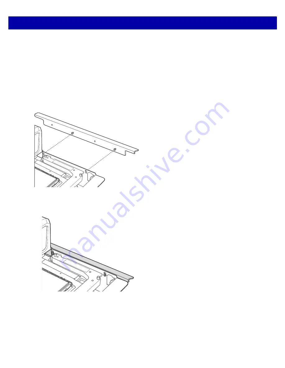
2.

Orient the adapter as shown in the illustration.

Figure 3-48    

Orient the Adapter

3.

Attach the side rail to the MP6000, and tighten using a Phillips head screwdriver.

Figure 3-49    

Attach the Adapter

Содержание MP6000

Страница 1: ...MP6000 INTEGRATOR GUIDE ...

Страница 2: ......

Страница 3: ...MP6000 INTEGRATOR GUIDE 72E 172632 06 Revision A November 2014 ...

Страница 4: ...licensed program in a network without written permission from Zebra The user agrees to maintain Zebra s copyright notice on the licensed programs delivered hereunder and to include the same on any authorized copies it makes in whole or in part The user agrees not to decompile disassemble decode or reverse engineer any licensed program delivered to the user or any portion thereof Zebra reserves the...

Страница 5: ...s RS 232 host connection to AUX 2 port leaves USB host port available for future use Programmable scale initial zero setting range IBM scale 3 byte status support Volume button disable feature Dual cable scale SASI only Wincor A B and RS 232 host interfaces see Table 2 4 on page 2 15 USB HID keyboard interface Drivers License Parsing some models Updated Host interface ports and cables 04 Rev A 5 2...

Страница 6: ...s Page 3 18 Speaker Wire Ferrite Placement step and figure Figures 3 43 and 3 44 installing Sensormatic coils Replace drawing with Figure 3 40 Lowering the Short Medium Long MP6000 into the Counter Diagrams for installing Sensormatic Coils Page 4 8 Added the Important note regarding newer firmware in the section Calibration Mode Exit Conditions Page 4 11 Important note about audit tallies Page 5 2...

Страница 7: ...v ...

Страница 8: ...vi MP6000 INTEGRATOR GUIDE ...

Страница 9: ...rted Auxiliary Hand held Scanner 1 8 EAS Devices 1 8 Scale Devices 1 8 USB Flash Drives 1 8 Customer Side Scanner CSS 1 8 Features of the MP6000 1 9 Optional Leak Platter European Configurations Only 1 13 Features Summary 1 13 Chapter 2 HOST INTERFACES AND CABLE PINOUTS Overview 2 1 Interfaces Components and Communication 2 2 POS Interfaces and Host Communication 2 2 Auxiliary Ports and Peripheral...

Страница 10: ...e Zero Pin 2 41 Connecting an IBM RS 485 Interface 2 43 IBM RS 485 Host Parameters 2 44 IBM Scale Port Addresses 2 49 Connector Pins 2 53 RS 232 AUX 1 2 53 Scale Display Port 2 53 RS 232 AUX 2 2 54 Checkpoint Interlock 2 54 AUX A B Stacked USB 2 54 POS 2 55 12V DC 2 55 Chapter 3 SITE PREPARATION AND INSTALLATION Overview 3 1 Site Preparation 3 2 Ventilation and Spacing Requirements 3 2 Service Acc...

Страница 11: ... If Required 3 39 Chapter 4 SCALE CALIBRATION MODELS WITH A SCALE ONLY Overview 4 1 Scale Calibration Procedure Scanner Scale Configurations Only 4 2 Scale Configurations 4 2 Identifying Firmware Version 4 2 Step 1 Electronic Entry into Calibration Mode 4 3 Firmware Versions Older Than v3 4 4 3 Firmware Versions Newer Than v3 4 4 3 Step 2 Program Legal Parameters 4 3 Legal Scale Units Unit Selecti...

Страница 12: ...on Scale and Medium Scale Platters 5 7 Installing Removing the Long Scale Platter 5 8 Scan Windows 5 9 Operating Modes 5 10 Programming the MP6000 5 10 Programming Management tools 5 10 Application Programming Interfaces 5 10 Programming Bar Codes 5 10 USB Staging Flash Drive 5 11 MP6000 Menu Structure for the USB Staging Flash Drive 5 11 Manually Staging Configuring MP6000 Devices 5 12 Loading Cl...

Страница 13: ...g Codes A 2 LED Display Notes A 2 Status Indicator Light A 2 Troubleshooting Assistance A 3 General Error and Warning Codes A 5 Scale Warning Codes A 6 Appendix B TECHNICAL SPECIFICATIONS Technical Specifications B 1 Appendix C HOST INTERFACE CHARACTER SETS Introduction C 1 RS 232 Character Sets C 2 Appendix D PARAMETER DEFAULT TABLE Appendix E COMMUNICATION PROTOCOLS Index ...

Страница 14: ...xii MP6000 INTEGRATOR GUIDE ...

Страница 15: ...how to change weight measurement calibrate the scale verify calibration and recognize errors Chapter 5 OPERATING THE SCANNER describes how to operate the MP6000 including buttons switches LED indicators and scanning Chapter 6 123SCAN2 provides information about configuring the MP6000 using the 123Scan2 utility Appendix A MAINTENANCE TROUBLESHOOTING AND ERROR CODES provides error warning codes trou...

Страница 16: ...ation MX101 PRODUCT REFERENCE GUIDE p n 72E 171320 xx provides general instructions for setting up operating maintaining and troubleshooting the MX101 digital scanner MP6000 MULTI PLANE IMAGING SCANNER REGULATORY GUIDE p n 72 171321 xx provides domestic and international regulatory information Advanced Data Formatting Programmer Guide p n 72E 69680 xx provides information on ADF a means of customi...

Страница 17: ...ons a Field Service Technician from Zebra or your authorized service provider may be sent to your location to perform the repair depending on your level of entitlement set forth in the service agreement Zebra is not responsible for any damages incurred during shipment if the approved shipping container is not used Shipping the units improperly can possibly void the warranty If you purchased your b...

Страница 18: ...viii MP6000 INTEGRATOR GUIDE ...

Страница 19: ...TER 1 PRODUCT OVERVIEW AND FEATURES Introduction This chapter includes the following topics Product Overview on page 1 2 Configurations on page 1 3 Peripherals on page 1 8 Features of the MP6000 on page 1 9 ...

Страница 20: ...canning Reads top bottom left right and cashier customer side bar codes Omni directional symbol orientation Optional integrated scale single dual interval Optional Checkpoint EAS antenna Optional integrated Sensormatic EAS coil antennas Optional Scale Display single dual head for scale installations Auxiliary scanner support USB and RS 232 High swipe speed for increased throughput User interface L...

Страница 21: ...N000M010US Multi plane scanner long with Checkpoint with CSS worldwide MP6010 LP000M010US Multi plane scanner long with Checkpoint with DL Parsing US CA MP6010 MN000M010US Multi plane scanner medium with Checkpoint with CSS worldwide MP6010 MP000M010US Multi plane scanner medium with Checkpoint with DL Parsing US CA MP6010 SN000M010US Multi plane scanner short with Checkpoint with CSS worldwide MP...

Страница 22: ...r OIML countries MP6200 MN000M010US Multi plane scanner medium with single interval scale with Checkpoint scale for US Puerto Rico Guam USVI British VI MP6200 MN000M01ABE Multi plane scanner Medium with single interval kg scale with Checkpoint scale Gravity Zone A for Belgium MP6200 MN000M01BBE Multi plane scanner Medium with single interval kg scale with Checkpoint scale Gravity Zone B for Belgiu...

Страница 23: ... Checkpoint Canada Mexico scale label MP6210 MN000M010EU Multi plane scanner medium with single interval scale with Checkpoint with CSS scale for EU countries MP6210 MN000M010NN Multi plane scanner medium single interval scale with Checkpoint with CSS scale for OIML countries MP6210 MN000M010US Multi plane scanner medium with single interval scale with Checkpoint with CSS scale for US Puerto Rico ...

Страница 24: ... Multi plane scanner medium with dual interval scale Drivers License Parsing with Checkpoint scale for US MP6510 LN000M010CM Multi plane scanner long with dual interval scale with Checkpoint with CSS scale for Canada Mexico MP6510 LN000M010EU Multi plane scanner long with dual interval scale with Checkpoint with CSS scale for EU MP6510 LN000M010NN Multi plane scanner long with dual interval scale ...

Страница 25: ...dium with dual interval scale Drivers License Parsing with Checkpoint with CSS scale for US Table 1 1 MP6000 Configurations Continued Configuration Description Notes 1 EU scales are legally accepted in the following countries Austria Belgium Bulgaria Cyprus Czech Republic Denmark Estonia Finland France Germany Greece Hungary Ireland Iceland Italy Liechtenstein Lithuania Luxembourg Latvia Malta Net...

Страница 26: ...parts of Europe available September 2014 USB Flash Drives Typical USB flash drive with Type A connector See USB Staging Flash Drive on page 5 11 Customer Side Scanner CSS The CSS MX101 is an optional integrated device that supports 1D and 2D bar code scanning The CSS unit replaces the MP6000 tower cover and can be installed on either side of the MP6000 Refer to the MX101 PRODUCT REFERENCE GUIDE p ...

Страница 27: ...SS and MP6000 Front View NOTE Refer to the MX101 Product Reference Guide p n 72E 171320 xx for information about the optional Customer Side Scanner CSS The CSS is shown in its default left side position but it can be moved to the other side at any time no tools required Horizontal Scan Window Volume Tone Control Button LED Array Bar Scale Zero Button EAS Deactivation Button Sensormatic only Vertic...

Страница 28: ... Channel also see Figure 3 46 on page 3 36 for Sensormatic coil routing Drainage Ventilation Holes Tower Bezel Tower Cover RS 232 AUX 1 0 0 Scale Display RS 232 AUX 2 AUX A B 2 POS 12V DC CKP I LOCK 1 Drainage Ventilation Holes 1 Checkpoint Interlock Port 2 Auxiliary USB Ports Strain Relief Groove for cables CSS Cable Channels ...

Страница 29: ...veling Screws 2 screws on opposite side 1 Leveling Screw Access Holes medium and short units only NOTE The tower bezel must be removed and the Tower Cover slid backwards to access the leveling screws 1 Leveling screws are an optional accessory To use leveling screws buy accessory kit MX301 SR00004ZZWR for standard length screws or accessory kit MX302 SR00004ZZWR for 1 in 25 mm extra length ...

Страница 30: ...1 12 MP6000 INTEGRATOR GUIDE Figure 1 6 Scale Displays Some Scanner Scale Configurations Only Single Head MX201 and Dual Head MX202 additional head added during installation 290 o 290 o ...

Страница 31: ...oubleshooting information and scale legal parameters during calibration 5 3 LED Array Bar Provides visual feedback for system statuses and alerts 5 2 Scale Zero Button Scale status LED and touch button provides scale status and allows user to zero the scale 5 4 Volume Tone Control Button User selectable settings for audible system indications Status LED and button 5 4 EAS Deactivation Button Senso...

Страница 32: ...nnel Cable routing channel for the scale cable 1 10 Drainage Ventilation Holes Outlet for spills 1 10 CSS Cable Channels Channels for routing CSS cables 1 10 3 16 Table 1 3 Description of Connectors Port Description RS 232 AUX 1 J7 See Table 2 3 on page 2 13 for description 0 0 J6 Scale Display port RS 232 AUX 2 J5 See Table 2 3 on page 2 13 for description CKP I LOCK J4 Checkpoint EAS Interlock A...

Страница 33: ...PRODUCT OVERVIEW AND FEATURES 1 15 ...

Страница 34: ...1 16 MP6000 INTEGRATOR GUIDE ...

Страница 35: ...0 to a host It also include host interface bar codes See Figure 1 1 on page 1 9 for locations of the interface connectors OPOS JAVAPOS settings are outside the scope of this guide For the Zebra SDK go to www motorolasolutions com windowssdk NOTE SDK supported functionality by communication protocol is listed in Appendix E COMMUNICATION PROTOCOLS ...

Страница 36: ...USB only Wireless auxiliary scanner support may be provided via a corded cradle as an auxiliary device Sensormatic controller via the RS 232 auxiliary port Dual cable scanner scale Via RS 232 AUX 1 or RS 232 AUX 2 ports see Figure 1 3 on page 1 10 and Table 2 3 on page 2 13 IMPORTANT Avoid inserting a POS cable in the AUX 1 or AUX 2 port NOTE SDK supported functionality by communication protocol i...

Страница 37: ...r access to these programming interfaces go to www motorolasolutions com windowssdk NOTE Only Zebra hand held scanners can be managed via 123Scan2 see Chapter 6 123SCAN2 and SMS through the MP6000 scanner NOTE SDK supported functionality by communication protocol is listed in Appendix E COMMUNICATION PROTOCOLS NOTE If the MP6000 is powered up with no interface cable present it reverts to no host m...

Страница 38: ...ply is required the MP6000 draws power from USB cable POS connection using USB Standard A 5V requires a CBA U51 S16ZAR cable between POS equipment standard device PC and MP6000 POS RJ 45 connector The MP6000 is USB device but requires an external power supply MP6000 does NOT draw power from USB cable AUX scanner connection using a Zebra USB hand held scanner requires a Zebra USB type A cable betwe...

Страница 39: ...he POS 3 If no Power Plus is used connect a 12V power supply Connecting the 12V power supply immediately turns the unit on 4 Select the USB device type by scanning the appropriate bar code see USB Device Type on page 2 6 5 To modify any parameter options a Scan the appropriate bar codes in the MP6000 Bar Code Programming Guide p n 72E 172633 xx or b Use 123Scan2 or c Use the 123Scan2 2D configurat...

Страница 40: ...re the scanner does not stall during power up due to a failure to enumerate USB If the scanner stalls recover it by installing the CDC INF file and reboot the MP6000 NOTE This guide includes limited parameter bar codes For ALL MP6000 programming bar codes refer to the MP6000 Bar Code Programming Guide p n 72E 172633 xx Table 2 1 USB Host Parameters Parameter Page Number USB Device Type IBM Table t...

Страница 41: ...HOST INTERFACES AND CABLE PINOUTS 2 7 USB Device Type continued IBM Table top USB ...

Страница 42: ...2 8 MP6000 INTEGRATOR GUIDE USB Device Type continued IBM Hand held USB ...

Страница 43: ...HOST INTERFACES AND CABLE PINOUTS 2 9 USB Device Type continued IBM OPOS IBM Hand held USB with Full Scan Disable ...

Страница 44: ...selected and the MP6000 has auxiliary scanners connected use ADF rules to program the auxiliary scanners to add a 500 msec pause to the end of the data to prevent the interleaving of bar code data from multiple scanners This works with standard RS 232 and SSI over RS 232 with the Send Raw Decode Data setting ...

Страница 45: ...HOST INTERFACES AND CABLE PINOUTS 2 11 USB Device Type continued CDC COM Port Emulation ...

Страница 46: ...ections NOTE For a list of supported scanner functionality by communication protocol Appendix E COMMUNICATION PROTOCOLS NOTE The MP6000 uses 6V RS 232 signal levels to accommodate long cable lengths and increased noise immunity RS 232 AUX 1 RS 232 AUX 2 POS 12V DC NOTE Interface cables vary depending on configuration Table 2 2 Host Connections Port Connection Options POS Unpowered USB p n CBA U51 ...

Страница 47: ...iliary scanner 3 USB auxiliary scanner 3 Dual Cable Scanner Scale and a Sensormatic Controller 3 2 Sensormatic Controller Dual Cable Scanner Scale 2 USB auxiliary scanner 3 USB auxiliary scanner 3 Third Party Scale Sensormatic Controller 4 Third Party Scale Sensormatic Controller USB auxiliary scanner3 USB auxiliary scanner3 1 Default setting 2 The Dual Cable Scanner Scale protocol is SASI 3 In al...

Страница 48: ...ale interface supports the industry standard SASI scale only protocol and communicates with a POS using a 9600 baud rate 7 data bits and even parity To set up the MP6000 and Dual Cable Scanner Scale 1 Attach the RJ 45 modular connector of the RS 232 scanner interface cable to the POS port on the MP6000 Connect the other end of the RS 232 scanner interface cable to the serial scanner port on the ho...

Страница 49: ...tandard RS 232 default 2 21 ICL RS 232 2 22 Wincor Nixdorf RS 232 Mode A 2 23 Wincor Nixdorf RS 232 Mode B 2 24 Olivetti ORS4500 2 25 Omron 2 26 OPOS JPOS 2 27 Fujitsu RS 232 2 28 CUTE 2 29 NCR Variant 2 30 Datalogic Variant 2 31 RS 232 Device Port Configuration AUX 1 Sensormatic and AUX 2 RS 232 Scanner default 2 33 Third Party Scale Disable Third Party Scale default Disable 2 38 Third Party Scal...

Страница 50: ... None Odd Odd Stop Bit Select One One One One ASCII Format 8 Bit 8 Bit 8 Bit 8 Bit Hardware Handshaking RTS CTS Option 3 None RTS CTS Option 3 RTS CTS Option 3 Software Handshaking None None None None Serial Response Timeout 9 9 Sec 2 Sec None None RTS Line State High Low Low Low No data to send Beep On BEL Disable Disable Disable Disable Transmit Code ID Yes Yes Yes Yes Data Transmission Format D...

Страница 51: ...ne Serial Response Timeout 9 9 Sec 9 9 Sec 9 9 Sec 9 9 Sec 9 9 Sec RTS Line State Low High High High High Beep On BEL Disable Disable Disable Disable Enable Transmit Code ID Yes Yes Yes Yes Yes Data Transmission Format Prefix Data Suffix Data Suffix Prefix Data Suffix Prefix Suffix Data Suffix Prefix STX 1002 None STX 1002 STX None Suffix ETX 1003 CR 1013 CR 1013 ETX 1003 ETX CR 1013 The CUTE host...

Страница 52: ...inal Specific Code ID Characters Code Type ICL Fujitsu Wincor Nixdorf Mode A Wincor Nixdorf Mode B OPOS JPOS UPC A A A A A UPC E E E C C EAN 8 JAN 8 FF FF B B EAN 13 JAN 13 F F A A Bookland EAN F F A A Code 39 C len None M M Code 39 Full ASCII None None M M Trioptic None None None None Code 32 None None None None Codabar N len None N N Code 128 L len None K K GS1 128 L len None P P Code 93 None No...

Страница 53: ...de 32 None None None None AE Codabar N len N len None None Code 128 K len L len 5 B3 GS1 128 P len L len 5 None None Code 93 L len None None None I 2 of 5 I len I len 1 B2 i D 2 of 5 H len H len 2 None None MSI O len None None None IATA H len H len 2 None IA GS1 Databar Variants None None None e0 GS1 Databar R4 GS1 Databar Limited RL GS1 Databar Expanded RX PDF417 None None 6 n a P MicroPDF417 Non...

Страница 54: ...t both scanner only and scanner scale versions Datalogic Variant NOTES 1 Scanning Standard RS 232 activates the RS 232 driver but does not change port settings e g parity data bits handshaking Selecting another RS 232 host type bar code changes these settings 2 The CUTE host disables all parameter scanning including Set Defaults If you inadvertently select CUTE scan Enable Parameter Bar Code Scann...

Страница 55: ...HOST INTERFACES AND CABLE PINOUTS 2 21 RS 232 Host Types continued Standard RS 232 ...

Страница 56: ...2 22 MP6000 INTEGRATOR GUIDE RS 232 Host Types continued ICL RS 232 ...

Страница 57: ...HOST INTERFACES AND CABLE PINOUTS 2 23 RS 232 Host Types continued Wincor Nixdorf RS 232 Mode A ...

Страница 58: ...2 24 MP6000 INTEGRATOR GUIDE RS 232 Host Types continued Wincor Nixdorf RS 232 Mode B ...

Страница 59: ...HOST INTERFACES AND CABLE PINOUTS 2 25 RS 232 Host Types continued Olivetti ORS4500 ...

Страница 60: ...2 26 MP6000 INTEGRATOR GUIDE RS 232 Host Types continued Omron ...

Страница 61: ...HOST INTERFACES AND CABLE PINOUTS 2 27 RS 232 Host Types continued OPOS JPOS ...

Страница 62: ...2 28 MP6000 INTEGRATOR GUIDE RS 232 Host Types continued Fujitsu RS 232 ...

Страница 63: ...HOST INTERFACES AND CABLE PINOUTS 2 29 RS 232 Host Types continued CUTE 2 ...

Страница 64: ...ble the NCR variant of the RS 232 host NCR Variant IMPORTANT There are several parameter options available with the NCR variant for RS 232 Refer to the MP6000 Bar Code Programming Guide p n 72E 172633 xx to manage the following NCR related parameters NCR Use Prefix NCR Prefix NCR Suffix NCR Use BCC NCR Interface ...

Страница 65: ...HOST INTERFACES AND CABLE PINOUTS 2 31 RS 232 Host Types continued RS 232 Host Datalogic Variant Scan the bar code below to enable the Datalogic variant of the RS 232 host Datalogic Variant ...

Страница 66: ...For that reason always remember to perform one of the functions below after scanning a device port parameter Cycle power to the scanner disconnect and re connect scanner cable or Use the MP6000 Reset button button combination to reboot the MP6000 When selecting any of the device port configuration options ensure the devices connected to the MP6000 correctly match the devices defined for the option...

Страница 67: ...HOST INTERFACES AND CABLE PINOUTS 2 33 RS 232 Device Port Configuration continued AUX 1 Sensormatic and AUX 2 RS 232 Scanner 00h ...

Страница 68: ...2 34 MP6000 INTEGRATOR GUIDE RS 232 Device Port Configuration continued AUX 1 Dual Cable Scale and AUX 2 RS 232 Scanner 01h ...

Страница 69: ...HOST INTERFACES AND CABLE PINOUTS 2 35 RS 232 Device Port Configuration continued AUX 1 Sensormatic and AUX 2 Dual Cable Scale 02h ...

Страница 70: ...2 36 MP6000 INTEGRATOR GUIDE RS 232 Device Port Configuration continued AUX 1 Third Party Scale AUX 2 Sensormatic 04h ...

Страница 71: ...le Third Party Scale functionality When disabled Third Party Scale LED Pin parameter 1295 and Third Party Scale Zero Pin parameter 1296 are ignored overridden Also see Price Computational Scale Interface Circuit Drawing on page 2 13 Options Enable Third Party Scale Disable Third Party Scale Enable Third Party Scale 1 ...

Страница 72: ...2 38 MP6000 INTEGRATOR GUIDE Third Party Scale continued Disable Third Party Scale 0 ...

Страница 73: ...arty Scale LED Pin Parameter 1295 This parameter defines the polarity of the LED Tare input pin that illuminates the scale LED This parameter has no effect if Third Party Scale parameter 1294 is disabled Options Active Low Active High Active Low 0 ...

Страница 74: ...2 40 MP6000 INTEGRATOR GUIDE Third Party Scale LED Pin continued Active High 1 ...

Страница 75: ...ty Scale Zero Pin Parameter 1296 This parameter defines the polarity of the zero output pin when the Scale Zero button is pressed This parameter has no effect if Third Party Scale parameter 1294 is disabled Options Active Low Active High Active Low 0 ...

Страница 76: ...2 42 MP6000 INTEGRATOR GUIDE Third Party Scale Zero Pin continued Active High 1 ...

Страница 77: ...an the appropriate scale port address IBM Scale Port Addresses on page 2 49 5 To modify any other parameter options scan the appropriate bar codes in the MP6000 Bar Code Programming Guide p n 72E 172633 xx 6 To prevent the IBM POS from configuring the MP6000 refer to the MP6000 Bar Code Programming Guide for information about RS 485 and IBM USB configuration beep scale and type directives NOTE For...

Страница 78: ...485 interface on the MP6000 2 The port numbers in Table 2 9 are no longer physical ports on the IBM POS NOTE This guide includes limited parameter bar codes For ALL MP6000 programming bar codes refer to the MP6000 Bar Code Programming Guide p n 72E 172633 xx Table 2 9 IBM RS 485 Port Parameters Parameter Page Number IBM Port Addresses None Selected default 2 45 Hand Held Scanner Emulation Port 9B ...

Страница 79: ...HOST INTERFACES AND CABLE PINOUTS 2 45 IBM Port Addresses None Selected ...

Страница 80: ...2 46 MP6000 INTEGRATOR GUIDE IBM Port Addresses continued Hand held Scanner Emulation Port 9B ...

Страница 81: ...HOST INTERFACES AND CABLE PINOUTS 2 47 IBM Port Addresses continued Non IBM Scanner Emulation Port 5B ...

Страница 82: ...2 48 MP6000 INTEGRATOR GUIDE IBM Port Addresses continued Tabletop Scanner Emulation Port 17 ...

Страница 83: ...HOST INTERFACES AND CABLE PINOUTS 2 49 IBM Scale Port Addresses The scale port address must be configured for the scale to operate on the IBM RS 485 bus The default is None Selected None Selected ...

Страница 84: ...2 50 MP6000 INTEGRATOR GUIDE IBM Scale Port Addresses continued Port 6A ...

Страница 85: ...HOST INTERFACES AND CABLE PINOUTS 2 51 IBM Scale Port Addresses continued Port 6B ...

Страница 86: ...2 52 MP6000 INTEGRATOR GUIDE IBM Scale Port Addresses continued Port 6E ...

Страница 87: ...I O signals are 5V TTL 9 GEN II only Scale Zero Out Zeros price computational scale when the Zero UI button is pressed if enabled I O signals are 5V TTL 10 GEN II only 12V 150mA Out Power output for price computational scale Table 2 11 RJ 11 Scale Display Pin Signal Name Direction Description 1 DEBUG_TXD Out Debug serial TX 2 5V Out Auxiliary 5V output 3 TXD Out Scale Display serial TX 3 3V TTL 4 ...

Страница 88: ...X 1 and AUX 2 The total combined current for the USB and RS 232 peripheral ports should be less than 750mA total auxiliary current Each individual port should not exceed 500mA Table 2 13 EAS Interlock Connector Pin Signal Name Direction Description 1 Interlock Out Checkpoint EAS Interlock 5V 4mA PNP collector out 2 GND N A Signal ground Table 2 14 Stacked USB Port Pin Signal Name Direction Descrip...

Страница 89: ...ctional Multiplexed serial TXD IBM A 5 RXD D Bidirectional Multiplexed serial RXD USB D 6 RTS IBM B Bidirectional Multiplexed serial RTS IBM B 7 CTS USB D Bidirectional Multiplexed serial CTS USB D 8 DOWNLOAD In POS download 9 N C N A 10 12V In Terminal 12VDC to MP6000 Power From Terminal Terminal systems vary in power capabilities Ensure your system power supply is capable of the MP6000 configura...

Страница 90: ...2 56 MP6000 INTEGRATOR GUIDE ...

Страница 91: ... in three industry standard sizes for more detailed information see Appendix B TECHNICAL SPECIFICATIONS Short no scale available Length 13 9 in 0 05 in 353 0 mm Width 11 5 in 0 05 in 292 0 mm Medium with or without scale Length 15 7 in 0 05 in 399 0 mm Width 11 5 in 0 05 in 292 0 mm Long with or without scale Length 20 0 in 0 05 in 508 0 mm Width 11 5 in 0 05 in 292 0 mm ...

Страница 92: ...ss Requirements The MP6000 was engineered to allow performance of all routine service and maintenance including scale zeroing and calibration without removing the scanner from the counter Service must be performed by a Zebra Certified Repair Provider who has completed the Service Repair Training course and if applicable the Scale Calibration Training course For MP6200 and MP6500 scanner scales dep...

Страница 93: ... modular line cord Figure 3 2 Power Supply If using the AC DC accessory power supply a 115V 230V outlet must be available in the checkstand near the scanner Grounding All POS equipment should be properly grounded and only a three prong IEC style line cord should be used with the AC DC accessory power supply If you are unsure how to verify proper ground of equipment in the checkstand ask a qualifie...

Страница 94: ...ccur Vertical Clearance For all configurations of the MP6000 the maximum height above the platter is 5 1 in the maximum depth below the platter is 4 08 in Tools No tools are required to install a MP6000 without a scale or a Checkpoint antenna The following tools are required to mount the Scale Display Ruler or similar measuring device Pencil or similar measuring device Drill 2 4 mm 3 32 in diamete...

Страница 95: ...e scanner scale being installed see Figure 3 30 Figure 3 34 and Figure 3 38 The counter cutout size should reflect the model also see page 3 31 for installation information Ergonomics Ensure the installation is designed for maximum comfort efficiency safety and ease of use Allow items to be directed within easy reach and a scanning area requiring no lifting or special orientation of items ...

Страница 96: ...sories page 3 7 3 Assemble the dual head Scale Display if applicable page 3 9 4 Install the Scale Display if applicable page 3 12 5 Connect the cables page 3 15 6 Install CSS if applicable page 3 16 7 Install the MP6000 scale in the checkstand page 3 25 8 Power up the MP6000 page 3 34 9 Lower and level the MP6000 in the checkstand page 3 31 10 Calibrate the scale if applicable see Chapter 4 SCALE ...

Страница 97: ... antennas disconnect from the current bioptic but leave in place b The RS 232 cable to the Sensormatic controller communications port use its run to assist replacing it 7 If a Scale Display is present a Make a note of how the current display was mounted and determine if the current placement can accommodate the new Scale Display Adjustments to the layout and cable run may be required b Unplug the ...

Страница 98: ...play is included it is recommended to mount it in an appropriate location preferably where the old display was mounted The cable should be routed through the checkstand If the unit includes a scale scale calibration is required If the unit includes EAS Sensormatic its coils require installation the large Sensormatic cable should be threaded from the controller box to the coils The Sensormatic RS 2...

Страница 99: ... Figure 3 5 Second Scale Display 2 Remove the adhesive backing of the required overlay and carefully secure it in place on the front face of the new display 3 Remove the four securing screws from the rear of the existing display before removing the front of the existing display complete with LCD and PCB Figure 3 6 Dismantling Existing Display NOTE This only applies when adding a second display hea...

Страница 100: ...g single head display 6 Place the short pole extension of the new display into the vacant slot in the rear cover of the existing display Figure 3 8 Short Pole Extension Figure 3 9 Rotation Limiting Tab NOTE There is a rotation limiting tab on the top and bottom surfaces of the pole extension see Figure 3 9 These need to be fitted one side or the other of the mating projection in the rear cover If ...

Страница 101: ...ace using the pole grip and two M3 x 12 self tapping screws supplied These are Phillips screw heads Figure 3 10 Secure in Place 8 Replace the case back of the existing original single head display using the four M3 x 18 self tapping screws removed earlier ...

Страница 102: ...nsider both the cashier and customer s viewing angle Both must see the weight value displayed Figure 3 11 Single Scale Display Dimensions Display Rotates Independently Approximately 290 o 3 0 in 75 0 mm 2 3 in 58 0 mm 4 5 in 115 0 mm 0 6 in 15 0 mm 3 1in 77 5 mm 6 1 in 155 0 mm 10 7 in 272 0 mm 290 o ...

Страница 103: ...LLATION 3 13 Figure 3 12 Dual Scale Display Dimensions Display Rotates Independently Approximately 290 o 2 8 in 70 0 mm 15 5 in 394 0 mm 10 5 in 267 0 mm 3 0 in 75 0 mm 6 1 in 155 0 mm 2 3 in 3 1 in 77 5 mm 2 3 in 57 5 mm 290 o ...

Страница 104: ...inals printer validation and paper roll slots access to replace consumables rolls etc Drill the required holes where the display is to be mounted see the template Figure 3 13 a The 19 mm 3 4 in diameter hole is optional to be used as a through hole for the cable pass through b The other two holes are pilot holes for the mounting screws and should be made to a diameter of 2 4 mm 3 32 in and a depth...

Страница 105: ...Fasten the Scale Display to the countertop a Place and align the display over the countertop screw holes b Place two screws through each screw hole in the base of the display c Drive both screws into the counter until tight d Route the cable accordingly and connect the Scale Display cable to port 0 0 Scale Display on the MP6000 BEFORE powering up the scanner scale see Figure 1 3 on page 1 10 5 Pow...

Страница 106: ...d on either the left or right side of the MP6000 Remove all hardware from the packaging The packaging contains the MX101 scan module and window MP6000 modified rear tower USB cable and MX101 identification label Regulatory Guide instructions to affix the label on the MP6000 and installation instructions not shown Figure 3 14 Parts of the MX101 Scan Module and Window Tower USB Cable Identification ...

Страница 107: ...queezing inward on both the left and right sides of the lower part of the tower bezel pushing its side snaps to disengage Slide the tower bezel up and lift out Figure 3 15 Removing the MP6000 Tower Bezel 2 Remove the MP6000 rear tower cover by gently pulling outwards on the tabs on either side then slide the tower cover back to remove Figure 3 16 Removing the MP6000 Tower Cover Squeeze Inward Towe...

Страница 108: ...MP6000 to which the MX101 should be installed The default is the customer s right side the side of the MX101 tower cover already open for the scan module to be inserted 5 Remove the scan window cover from the CSS tower by squeezing the snaps shown below The snaps are squeezed from inside the tower cover Figure 3 18 Removing the Scan Window Cover NOTE See Installing the MX101 on the Customer s Left...

Страница 109: ...over and push into place Figure 3 19 Inserting the Scan Module 7 Snap the scan window cover into place on the tower over the CSS scan window Figure 3 20 Snapping the Scan Window Cover in Place Scan Module CSS Tower Cover Grommets 3 Grommet Sockets 3 Module Installed NOTE Ensure you hear and feel three distinct snaps one for each snap mechanism lower front rear to ensure a snug fit in the rear towe...

Страница 110: ...RATOR GUIDE 8 Connect the USB cable to the top USB auxiliary port recommended on the MP6000 Route the cable into the side cable slots as shown Figure 3 21 Connecting the USB Cable Top USB Auxiliary Port Side Cable Slots ...

Страница 111: ...re the cable is clipped into the scan module plastic cable clip directly below the USB port Figure 3 23 Connecting the Cable Cable Slots Service Loop Cable Slots NOTE The path through the cable slots is not intuitive Send the cable towards the left of the tower as shown even though the CSS module is on the right Take up all the slack outside the MP6000 chassis so the CSS cable cannot be pinched by...

Страница 112: ...dule Snaps should click together When the tower cover is replaced the module locks into the grommet compression ribs on the MP6000 inner tower Figure 3 24 Replacing the Tower Cover 12 Replace MP6000 tower bezel Snap down into place Figure 3 25 Replacing the MP6000 Tower Bezel Installing the MX101 on the Customer s Left Side of the Tower Cover To install the MX101 on the left side of the MP6000 ...

Страница 113: ... Right Side Default of the Tower Cover on page 3 17 3 Insert the scan module into place facing out of the left side opening of the CSS tower cover Ensure the grommets on the scan module align with the sockets in the tower cover and push into place 4 Snap the scan window cover into place on the tower over the scan window See page 3 19 for diagrams 5 Connect the USB cable to the top USB port recomme...

Страница 114: ...r is replaced the module locks into the grommet compression ribs on the MP6000 9 Replace MP6000 tower bezel Snap down into place Affixing the Identification Label Peel the label from its backing Figure 3 28 Peel Off Backing Cable Slots for Left Side Installation Scan Module Cable Clip NOTE The path through the cable slots is not intuitive Send the cable towards the right of the tower as shown even...

Страница 115: ... based on the MP6000 model being installed After cutting the edges should be clean and straight with all burrs and splinters removed The MP6000 is 11 5 in wide If replacing a pre existing scanner in a checkstand that is 12 in wide we recommend a Trim Filler Kit to fill in the gap in the checkstand see Trim Kit Installation If Required on page 3 38 The MP6000 is 4 in deep If replacing a pre existin...

Страница 116: ... 14 03 in 0 06 in 356 2 mm 1 5 mm 14 03 in 0 06 in 356 2 mm 1 5 mm 11 63 in 0 06 in 295 3 mm 1 5 mm Max R 0 25 in 6 35 mm 2x Cashier Side Optional Leveling Feet Locations Max 0 25 in 6 4 mm Max 4 0 in 101 6 mm 1 75 in 25 in 44 6 mm 6 6 mm Support Rails 1 75 in 25 in 44 6 mm 6 6 mm IMPORTANT Use the support rails as shown and not a shelf If liquid spills it pools on a shelf ...

Страница 117: ...Figure 3 32 MP6000 Short Unit No Scale Top View Dimensions Figure 3 33 MP6000 Short Unit No Scale Side View Dimensions 13 90 in 353 1 mm 11 50 in 292 2 mm 5 1 in 128 5 mm 4 00 in 101 6 mm 14 03 in 0 06 in 356 2 mm 1 5 mm Counter Opening Optional leveling screw kit MX301 SR00004ZZWR ...

Страница 118: ...m 6 6 mm 15 83 in 0 06 in 402 mm 1 5 mm 1 75 in 25 in 44 6 mm 6 6 mm Max R0 25 in 6 35 mm 2X Cashier Side 11 63 in 0 06 in 295 3 mm 1 5 mm Max 4 00 in 101 6 mm Optional Leveling Feet Locations Max 2 00 in 50 8 mm 1 75 in 0 25 in 44 5 mm 6 6 mm 1 75 in 0 25 in 44 5 mm 6 6 mm Support Rails IMPORTANT Use the support rails as shown and not a shelf If liquid spills it pools on a shelf ...

Страница 119: ...igure 3 36 MP6000 Medium Unit Side View Dimensions Figure 3 37 MP6000 Medium Unit Top View Dimensions 5 1 in 128 5 mm Counter Opening 4 00 in 101 6 mm 15 83 in 0 06 in 402 mm 1 5 mm Optional leveling screw kit MX301 SR00004ZZWR or MX302 SR00004ZZWR 15 66 in 397 8 mm 11 50 in 292 2 mm ...

Страница 120: ...n 0 75 in Max 1 22 in Min 19 1 mm Max 31 0 mm Cashier Side 20 13 in 0 06 in 511 2 mm 1 5 mm 0 38 in 0 03 in 9 5 mm 0 8 mm 20 13 in 0 06 in 511 2 mm 1 5 mm Counter Opening 5 1 in 128 5 mm Counter to Top of Unit 4 00 in 101 6 mm Max 18 63 in 473 1 mm 0 38 in 0 03 in 9 5 mm 0 8 mm NOTE The countertop after routing must have sufficient strength to support the scanner and the loads placed on top of it ...

Страница 121: ...he Customer Side Scanner MX101 on page 3 16 e Sensormatic coil or Checkpoint EAS antenna was installed if applicable See Install Sensormatic Coils on page 3 34 or Install Checkpoint Antenna on page 3 37 2 Verify checkstand dimensions shown in Figure 3 30 Figure 3 34 and Figure 3 38 respectively 3 Lower scanner in checkstand as follows a Remove the platter to access the front handle of the device s...

Страница 122: ...ews and the platter must be flush with the surrounding checkstand If the MP6000 rocks remove it and adjust the checkstand supports screws If the MP6000 still rocks continue to remove the device and adjust the supports until it sits solidly in the checkstand When the platter is flush its leading edge should be slightly below the checkstand and the trailing edge should be slightly above the checksta...

Страница 123: ...ack Figure 3 42 Adjusting Leveling Screws When the platter is flush its leading edge should be slightly below the checkstand and the trailing edge should be slightly above the checkstand Leveling Screw Holes Under Platter Leveling Screw Holes Under Bezel Medium Unit Short Unit Leveling Screw Holes Under Bezel Leveling Screw Holes Under Bezel Leveling Screw Holes Under Platter Leveling Screw Holes ...

Страница 124: ... room the temperature is 70 F 20 C Install Sensormatic Coils The horizontal antenna is installed below the platter on the middle housing affixed to the housing with screws The vertical antenna is installed behind the vertical glass also affixed to the scanner with screws The coil tail wires with connectors should be properly routed alongside the scanner to which the Sensormatic controller box lead...

Страница 125: ...oil 4 Install the vertical coil a Unplug the USB cap see Staging USB Flash Drive Cap Port on page 1 11 and move out of the way it may interfere with the coil during this installation b Position the coil in front of and centered around the vertical window c Push it straight back until the top of the coil rests against the stops Figure 3 45 Installing the Vertical Coil d Replace the USB cap USB Cap ...

Страница 126: ...ve the wires free under the MP6000 for a Sensormatic representative to make the connection to the controller Figure 3 46 Routing the Coil Through the Key Hole 6 Replace the MP6000 tower bezel 7 Replace the MP6000 platter 8 Connect the Interlock cable supplied by Sensormatic to the J7 or J5 port Horizontal Sensorrmatic Cable Pinch Point NOTE The Interlock cable is one of the free cables noted in St...

Страница 127: ...e routed as pictured hanging several inches below the MP6000 so that the Checkpoint controller lead wires can tie into the antenna A cable with two additional leads is available to support Interlock features The Interlock cable assembly part number is CB000002A01 orderable as CBA A54 S01EAR includes a connector and a pigtail for Checkpoint Contact your local Checkpoint representative to install th...

Страница 128: ... the MP6000 It should be installed in the downstream side of the conveying goods The trim adds 0 5 in 1 2 cm to the width of the MP6000 The kit includes one metal trim and two Phillips head screws M4 x 8mm To install the trim 1 Insert the two screws provided in the rail 2 Orient the adapter as shown in the illustration Figure 3 48 Orient the Adapter 3 Attach the side rail to the MP6000 and tighten...

Страница 129: ...SITE PREPARATION AND INSTALLATION 3 39 MP6000 Mounting Frame If Required Figure 3 50 Installing the Mounting Frame 1 2 3 ...

Страница 130: ...3 40 MP6000 INTEGRATOR GUIDE ...

Страница 131: ...des are located in the MP6000 Bar Code Programming Guide p n 72E 172633 xx Table 4 1 Scale Parameters in this Chapter Parameter Parameter Number Parameter Name Default Page Number Legal Scale Units 995 Kilograms default 4 13 Pounds 4 14 Scale Display Configuration 986 Disable Scale Display default 4 16 Enable Scale Display 4 15 Legal Scale Dampening Filter 996 Higher Vibration Sensitivity 4 17 Low...

Страница 132: ...ration procedure 3 The scale can be calibrated without a Scale Display However if a Scale Display is used Enable Scale Display Configuration page 4 15 must be scanned to enable the display and its port The default Scale Display configuration is Disabled 4 The MP6000 scanner scale must remain powered for a minimum of 15 minutes after a cold power start prior to performing the calibration procedure ...

Страница 133: ...tion process with Step 2 Program Legal Parameters on page 4 3 Step 2 Program Legal Parameters Sealable and legal parameters Unit Selection and Dampening Filter Setting can only be programmed changed when the MP6000 is placed into Calibration Mode There is no requirement to change these values they can remain in the default or present state However if there is a need to change their values they mus...

Страница 134: ...most sensitive to vibration 1 Low factory default 2 Very Low 3 Ultra Low The lower the number the more sensitive the scale is to vibration The higher the number the slower the scale may operate Step 3 Calibration at NO LOAD When Calibration Mode enters properly the Scale Display blinks between CAL00 and CAL _ _ and the 7 segment display scrolls C00Lb or C00g Scale calibration can begin 1 Ensure th...

Страница 135: ...its of measure programmed place 25 lb or 11 kg on the scale Ideally these weights should be grouped in the center of the scale Figure 4 1 Figure 4 1 A Center of Scale Location and B Center of Scale Location with Platter Installed IMPORTANT This step of the calibration procedure must be completed within 30 seconds or 90 seconds for Firmware Version before 3 4 See Identifying Firmware Version If thi...

Страница 136: ... kg weights on the scanner as shown in Figure 4 3 two 5 kg weights centered on the center of the scale and one 1 kg weight on top between the two 5 kg weights Figure 4 3 Weight Calibration Configuration for Kilograms 2 Press the Scale Zero button with the weights on the platter 3 Calibration continues with Step 5 Calibration Success or Failure on page 4 7 Calibration was either successful or faile...

Страница 137: ...nd the Scale Display blinks HOLD for the entire 90 second time period and then times out This condition does not display a calibration failure because the process was unable to find a zero weight threshold This may occur if the platter was not re installed or seated correctly or if the weight on the scale is outside a 2 maximum capacity range 0 6 lb or 0 3 kg It can also be a mechanical issue if t...

Страница 138: ...e order Use the appropriate table based on US lb or metric scales kg using applicable tolerance for single or dual interval scale models Table 4 3 Tests to Verify Scale Accuracy Test Description Increasing Load Test This test verifies accurate weight measurement with increasing weights placed incrementally on the scale s platter without returning weight to zero Over Capacity Test This test verifie...

Страница 139: ...0 00 01 lb 005 lb Table 4 5 Verification Tests for Metric Scale Verification Test for Metric Scale Applied Load kg Indication Applied Load Within Applicable Tolerances All Tolerances Are All Tolerances Are Acceptance Single Int Acceptance Dual Int Increasing Load Test 0 000 0 000 0 0 kg 0 0 kg 0 100 0 100 0025 kg 001 kg 2 500 2 500 0025 kg 002 kg 5 000 5 000 005 kg 003 kg 10 000 10 000 005 kg 005 ...

Страница 140: ... to Zero Test 0 000 0 000 0 0 kg 0 0 kg Shift Test see Figure 4 4 5 00 Position 1 5 000 005 kg 003 kg 5 00 Position 2 5 000 005 kg 003 kg 5 00 Position 3 5 000 005 kg 003 kg 5 00 Position 4 5 000 005 kg 003 kg Table 4 5 Verification Tests for Metric Scale Continued Verification Test for Metric Scale Applied Load kg Indication Applied Load Within Applicable Tolerances All Tolerances Are All Toleran...

Страница 141: ...nter C legal parameter counter P used for scale verification can be shown on the Scale Display or the 7 segment display 1 Press and hold the Scale Zero button for three seconds to access the calibration tallies not within Calibration mode a C and P tallies blink on the Scale Display and or scroll on the 7 segment display i C represents the number of times the scale reached Calibration Success on p...

Страница 142: ...mation as required by local Weight Measures Regulations or where required by law NOTE 1 This feature is inhibited when the unit is in a scale Calibration Mode NOTE 2 If units of weight measure was modified i e kg to lb or lb to kg the parameter counter is incremented by two in the audit tally This is because the Automatic Zero Setting legal parameter is being enabled when going from lb to kg and d...

Страница 143: ... unit below to set the legal weight units for the MP6000 Scan Kilograms for metric units scan Pounds for the US units Kilograms 0 NOTE Refer to the MP6000 Bar Code Programming Guide p n 72E 172633 xx for all programming bar codes for the MP6000 scale IMPORTANT The scale must be in a calibration mode to change this parameter ...

Страница 144: ...4 14 MP6000 INTEGRATOR GUIDE Legal Scale Units continued Pounds 1 ...

Страница 145: ...WITH A SCALE ONLY 4 15 Scale Display Configuration Parameter 986 Scan Enable Scale Display Configuration below to enable the Scale Display port The Scale Display port is disabled by default Enable Scale Display Configuration 1 ...

Страница 146: ...4 16 MP6000 INTEGRATOR GUIDE Scale Display Configuration continued Disable Scale Display Configuration 0 ...

Страница 147: ...ode below to set the vibration sensitivity of the scale The lower the number value the more sensitive the scale is to vibration The scale must be in a Calibration Mode to program this parameter Values 0 Higher most sensitive to vibration 1 Low factory default 2 Very Low 3 Ultra Low Higher Vibration Sensitivity 0 ...

Страница 148: ...4 18 MP6000 INTEGRATOR GUIDE Parameter 996 continued Low Vibration Sensitivity 1 ...

Страница 149: ...SCALE CALIBRATION MODELS WITH A SCALE ONLY 4 19 Parameter 996 continued Very Low Vibration Sensitivity 2 ...

Страница 150: ...4 20 MP6000 INTEGRATOR GUIDE Parameter 996 continued Ultra Low Vibration Sensitivity 3 ...

Страница 151: ...ON Weight reading Under zero No change No change None Flashing All dashes Over range condition weight is greater than 30 09 lb or weight is greater than 15 045 kg No change No change None OFF EEEEE Weight unstable No change No change None OFF Numerical values blank but measurement unit icons lb or kg remain on Scale Zero button press If zero operation fails it scrolls U12 Red Warning if zero opera...

Страница 152: ... blinks CAL11 with kg icon illuminated Step 5 Calibration Success or Failure Blinks between CAL P PASS and CAL S save legal parameter settings Any step Calibration fails blinks CAL F Between calibration steps No change No change No change Off Blinks HOLD while taking a measurement No platter installed at Step 3 Calibration at NO LOAD No change No change Persistent short beep tone at 1Hz No change ...

Страница 153: ...e Seven segment test runs and displays 00 000 all icons illuminated for three seconds Blank for one second 99 999 all icons illuminated for three seconds Blank for one second Normal display Audit Tally Press and hold Scale Zero button for greater than three seconds when not in a Calibration Mode Repeated scroll C then P No change None No change Blinks between C and P In Bootloader Mode No change O...

Страница 154: ...4 24 MP6000 INTEGRATOR GUIDE ...

Страница 155: ...ING THE SCANNER Overview This chapter describes how to operate the MP6000 including information about indicators LEDs beeper etc beeper speaker user buttons weighing items and the 7 segment character diagnostic display ...

Страница 156: ...ack for system statuses and alerts The LED has an array of five bi color green red LEDs and depending on the condition the entire LED bar illuminates or section of the bar illuminates The LED illuminates in the following situations Successful bar code decodes System warnings Error conditions The error illumination remains lit until all errors are resolved System idle See Table 5 1 on page 5 20 for...

Страница 157: ... through the display When a message is completed the display pauses for two seconds The message repeats continuously If the message is an error or warning it repeats until the issue is resolved If the message is related to scale calibration it repeats until calibration is completed If the message is related to the CAL PAR display it repeats until the inspector tester releases the Scale Zero button...

Страница 158: ... of a bar code and Sensormatic beep Error conditions Processing a request that takes an extended amount of time e g scanning a sequence of parameter bar codes This audible indication informs the user that the scanner is working and not malfunctioning To adjust volume and tone Press and release the Volume Tone button to sound the current scanner beep volume level Press and release the Volume Tone b...

Страница 159: ...c EAS device The LED is yellow amber and can be on flashing or off See Beeper and LED Indicators on page 5 20 for detailed indications Soft Reset Buttons Figure 5 6 Soft Reset Buttons A soft reset of the MP6000 can be initiated by pressing the Scale Zero and EAS buttons simultaneously for 10 seconds A two second beep sounds then a system reset is performed ...

Страница 160: ... Single interval weight capacity 0 00 30 00 lb at a resolution of 0 01 lb 0 000 15 000 kg at a resolution of 0 005 kg Dual Interval Range Scales A dual range scale changes resolution after a certain weight is reached For example 2g until 6kg 5g above 6kg Dual Interval weight capacity 0 000 12 00 lb at a resolution of 0 005 lb then 12 00 30 00 lb at a resolution of 0 01lb 0 000 6 000 kg at a resolu...

Страница 161: ...orner of the platter to lift it slightly Use your fingers under the platter to lift it up and out Figure 5 7 Removing Short Platter To install the platter drop the tower end down into the unit and lay it flat Installing Removing the Long Non Scale and Medium Scale Platters These platters have a lip at the cashier end which can be gripped for lifting To install the platter s drop the tower end of t...

Страница 162: ...tter on a long MP6000 with a scale 1 Line up the hooks on the platter with the notches in top scale frame 2 Drop the platter straight down on scale top frame 3 Slide the platter forward engaging the hooks 4 Drop the rear of the platter onto rear scale top frame pegs Figure 5 8 Installing the Long Platter MP6000 With Scale 1 2 3 4 Long Scale Platter Scale Top Frame ...

Страница 163: ...ng difficult symbols e g truncated poor contrast and damaged bar codes is accomplished in both vertical and horizontal windows in all six sided orientations See Scanning on page 5 15 for more information The horizontal window on the platter is clear scratch proof sapphire built for long term reliability and clarity and is impervious to scratches The vertical window is chemically tempered and can s...

Страница 164: ...23Scan2 plug in containing scanner firmware Load Directive file with programming details like trigger information Staging flash drive reprogramming USB Staging Flash Drive on page 5 11 Application Programming Interfaces Zebra Scanner SDK APIs CoreScanner APIs Zebra Scanner OPOS JPOS APIs WMI Interfaces For access to the APIs go to www motorolasolutions com windowssdk Programming Bar Codes With the...

Страница 165: ...y parameter settings and firmware from the MP6000 to the USB flash drive for cloning to another device or viewing in 123Scan2 When Option 1 is available the 7 segment display shows a 1 and one beep sounds Option 2 Load a USB flash drive configuration to the MP6000 Load the parameter settings and firmware if present from the staging USB flash drive to this MP6000 When Option 2 is available the 7 se...

Страница 166: ... see Figure 5 10 Two external ports on the side of the device One internal port accessible by removing platter The internal port sits straight up and includes a cap cover which must be replaced when the drive is not in use A missing or incorrect placement of the cap does not allow the platter to sit properly when replaced Figure 5 10 USB Port Under the MP6000 Platter Figure 5 11 USB Ports on the M...

Страница 167: ...g bar _ This means the device is working When the process is complete time varies three success beeps high low high or four failure beeps sound and the scrolling bar stops Removing the staging flash drive at this point sounds the success or failure beeps again from the last operation performed NOTE The USB flash drive must be at least 2 5 in 63 5 mm long to be accessible for removal after insertio...

Страница 168: ... Drive Wizard from any 123Scan2 screen click Tools Staging Flash Drive MP6000 only Create Staging Flash Drive Files Approved USB Flash Drives for the Flash Drive Well When using the MP6000 flash drive well located under the MP6000 platter the USB flash drive must meet the specifications below to be accessible easily inserted into and removed from the well Maximum thickness 43 in 11 mm Maximum widt...

Страница 169: ...on but automatically turns off when the object is removed When the object presented in the field of view includes a bar code the MP6000 scans the bar code and if the bar code is successfully decoded the illumination LEDs immediately turn off when the object is removed Position the bar code anywhere within the MP6000 s field of view Figure 5 12 Scanning with the MP6000 The scanner beeps to indicate...

Страница 170: ...nds remove the item from the platter remove the platter and check for debris underneath If there is debris remove it Replace the platter and press the Scale Zero button to reset the scale Wait for 0 00 lb 0 000 kg to display on the Scale Display and weigh the item again Raised Rail NOTE If the Scale Display does not show 0 00 lb 0 000 kg clear all items off the platter and zero the scale by touchi...

Страница 171: ...ponsibility to match these settings with the installed equipment Enabling EAS without EAS equipment or with the wrong equipment installed displays an EAS error message See Beeper and LED Indicators on page 5 20 and Diagnostic LED 7 segment Display Error and Warning Codes on page A 2 for beeper warning and error messages Also refer to the MP6000 Bar Code Programming Guide p n 72E 172633 xx for EAS ...

Страница 172: ...er includes a custom vertical and horizontal high inductance antenna The horizontal antenna is installed below the platter on the middle housing and is affixed to the housing with screws The vertical antenna resides behind the vertical glass and is also affixed to the scanner with screws See Install Sensormatic Coils on page 3 34 Sensormatic EAS should always be enabled There is no synchronization...

Страница 173: ...Soft Tags Labels Deactivation of soft tags alerts the user with audible Geiger counter beeps Deactivation of soft tags synchronized with a bar code scan alerts the user with audible Geiger counter beeps Soft tags can be disabled and they can also be reset using a Sensormatic tag re setter ...

Страница 174: ...ge Rule saved Rule entry mode exited Criteria or action cleared High Low Low Beeps Green No change All criteria or actions cleared for current rule continue entering rule Last rule deleted Low Beep Green No change Delete last saved rule The current rule is left intact All rules deleted Low High High Beeps Green No change All rules are deleted ADF out of memory Low High Low High Beeps Red No change...

Страница 175: ...ess the Scale Zero and Volume Tone again and release 5 long beeps sound No change No change After final 5 long beeps sound scale calibration is entered Press and release EAS button Click No change EAS is enabled LED is amber If EAS is enabled button press activates tag manual deactivation Code 39 Buffering Code 39 character added into buffer High Low Beeps No change No change New Code 39 data was ...

Страница 176: ...gress Firmware Download has multiple states The LEDs during these states are During firmware data download transfer no LED control After reboot firmware is installed LED blinks red fast After complete normal power up beep Parameter Programming Parameter entry error Low High Beeps Red No change Input error incorrect bar code programming sequence or Cancel scanned Parameter number entry expected Hig...

Страница 177: ... None No change Power up System reboot Loud two seconds beep No change for 10 seconds Red for last two seconds No change After holding the EAS and Volume buttons for 10 seconds the MP6000 reboots Bar code decoded Off Low Medium High two tone beep or TBD tone programmable Fan out LED sequence No change MP6000 LEDs arranged in a linear fashion will turn on in sequence Center then the two immediate s...

Страница 178: ... reached it wraps and begins at the lowest volume level Press and hold Volume Tone button for two seconds Annunciates decode tone No change Button LED blinks for two seconds Decode tone changes Subsequence decode tones are heard every second if continuously held Decode tones cycle Decode tone change Describes action above Button click decode beep at next tone wrap No change No change After holding...

Страница 179: ...ort options include programmed parameters asset tracking information and proof of scanner output Additionally 123Scan can display scanned bar code data including non printable characters It can display optimize and save pictures from an imaging scanner It can also upgrade scanner firmware automatically check online to enable support for newly released products generate a single 2D bar code for one...

Страница 180: ...can2 html Scanner SDK Other Software Tools and Videos Tackle all your scanner programming needs with our diversified set of software tools Whether you need to simply stage a device or develop a fully featured application with image and data capture as well as asset management these tools help you every step of the way To download any of the free tools listed below go to www MotorolaSolutions com S...

Страница 181: ...ge A 1 Troubleshooting on page A 2 Diagnostic LED 7 segment Display Error and Warning Codes on page A 2 General Error and Warning Codes on page A 5 LED Display Notes on page A 2 Scale Warning Codes on page A 6 Maintenance Clean the housing and glass with a damp cloth and if necessary a non ammonia based detergent Do not allow any abrasive material to touch the screen ...

Страница 182: ...oll when the Scale Zero button is held for three or more seconds An error message displays when a fault condition exists A power cycle is required Verify that the subsystems and auxiliary devices are operational A warning message displays when a warning condition exists The power sequence pauses until the issue is resolved For scale firmware version 1 04F for applicable countries Scrolling CAL num...

Страница 183: ...optional pole display scale units only for proper seating in their respective connectors 3 Inspect internal cables a Scale Units Only remove platter and confirm the scale communication cable is fully seated within the connector in the scale unit if necessary remove the unit from the counter top Figure A 1 Scale Connector 4 Remove tower bezel front housing and tower cover back cover inspect the cab...

Страница 184: ...move any objects from the platter or near the unit and re apply power to the MP6000 and attached equipment POS hand held scanner 8 Wait for the unit to boot and listen for start up audio indicators 9 If the LED display codes persist contact your Zebra qualified Service Provider LED PCB Underneath Cover UI PCB Underneath Cover ...

Страница 185: ...t Limit warning U9 Image Sensor Warning either U10 Vertical Image Sensor warning U11 Horizontal Image Sensor warning U16 Sensormatic EAS Offline warning U17 Host Protocol warning U18 Left Channel IR object detection failure U19 Left auxiliary board warning U20 Right auxiliary board warning U25 Right Channel IR object detection failure U27 User Interface button interface failure U29 EAS Communicati...

Страница 186: ...inutes If this persists re calibrate the scale NOTE 1This fault code annunciates if a weight greater than 4 5 lb or 2 25 kg is left on the weighing surface while the scale comes up from a reset or cold power start If this occurs clear it by removing the weight NOTE 2The fault code annunciates if the scale resets or upon a cold reset of the MP6000 system and the platter is not installed It clears w...

Страница 187: ...e Scale Display is faulty or the internal circuitry of the Scale Display is faulty The Scale Display and cable are a single Line Replaceable Assembly FRU NOTE In most applications p n MX201 SR00004ZZWW can be ordered as a replacement U24 Scale Motion Fault This condition occurs when the scale detects constant motion on the weighing surface for an extended duration of time This is a latched fault m...

Страница 188: ...A 8 MP6000 INTEGRATOR GUIDE ...

Страница 189: ...edium scanner and scanner scale Length 15 7 in 0 05 in 399 0 mm Width 11 5 in 0 05 in 292 0 mm Depth 4 0 0 08 in 101 6 2 mm Height Above platter 5 1 in max Long scanner and scanner scale Length 20 0 in 0 05 in 508 0 mm Width 11 5 in 0 05 in 292 0 mm Depth 4 0 0 08 in 101 6 2 mm Height Above platter 5 1 in max Weight NOTE Weight includes platter but not cables or power supply Short 12 7 lb 5 8 kg M...

Страница 190: ...heral ports Checkpoint interlock port Scale Display port Internal scale port Scale 30 lb in 0 01 lb increments 15 kg in 5 g increments Maximum static weight 300 lb 136 kg Scale can be added after scanner installation most countries Single cable and dual cable protocols Options Dual interval Zebra scale 0 12 lb in 0 005 lb increments and 12 30 lb in 0 01 lb increments 0 6 kg in 2 g increments and 6...

Страница 191: ...motorolasolutions com 123Scan Application Development Tools Zebra Scanner SDK APIs CoreScanner APIs Zebra Scanner OPOS JPOS APIs WMI interfaces Peripherals and Accessories Optional CSS The CSS enables shoppers to scan paper plastic loyalty cards or from a mobile device simultaneously while a cashier scans other items Scale Display Enables indication of zero status and gross weight indication for b...

Страница 192: ...B 4 MP6000 INTEGRATOR GUIDE ...

Страница 193: ...APPENDIX C HOST INTERFACE CHARACTER SETS Introduction You can assign the values in Table C 1 as prefixes or suffixes for ASCII character data transmission ...

Страница 194: ...racter 1000 U NUL 1001 A SOH 1002 B STX 1003 C ETX 1004 D EOT 1005 E ENQ 1006 F ACK 1007 G BELL 1008 H BCKSPC 1009 I HORIZ TAB 1010 J LF NW LN 1011 K VT 1012 L FF 1013 M CR ENTER 1014 N SO 1015 O SI 1016 P DLE 1017 Q DC1 XON 1018 R DC2 1019 S DC3 XOFF 1020 T DC4 1021 U NAK 1022 V SYN 1023 W ETB 1024 X CAN 1025 Y EM 1026 Z SUB 1027 A ESC 1028 B FS ...

Страница 195: ... C 1036 D 1037 E 1038 F 1039 G 1040 H 1041 I 1042 J 1043 K 1044 L 1045 1046 1047 O 1048 0 0 1049 1 1 1050 2 2 1051 3 3 1052 4 4 1053 5 5 1054 6 6 1055 7 7 1056 8 8 1057 9 9 1058 Z 1059 F Table C 1 Character Sets Continued Prefix Suffix Value Full ASCII Code 39 Encode Character RS 232 ASCII Character ...

Страница 196: ...E E 1070 F F 1071 G G 1072 H H 1073 I I 1074 J J 1075 K K 1076 L L 1077 M M 1078 N N 1079 O O 1080 P P 1081 Q Q 1082 R R 1083 S S 1084 T T 1085 U U 1086 V V 1087 W W 1088 X X 1089 Y Y 1090 Z Z Table C 1 Character Sets Continued Prefix Suffix Value Full ASCII Code 39 Encode Character RS 232 ASCII Character ...

Страница 197: ...00 D d 1101 E e 1102 F f 1103 G g 1104 H h 1105 I i 1106 J j 1107 K k 1108 L l 1109 M m 1110 N n 1111 O o 1112 P p 1113 Q q 1114 R r 1115 S s 1116 T t 1117 U u 1118 V v 1119 W w 1120 X x 1121 Y y Table C 1 Character Sets Continued Prefix Suffix Value Full ASCII Code 39 Encode Character RS 232 ASCII Character ...

Страница 198: ...00 INTEGRATOR GUIDE 1122 Z z 1123 P 1124 Q 1125 R 1126 S 1127 RS 232 Undefined 7013 RS 232 ENTER Table C 1 Character Sets Continued Prefix Suffix Value Full ASCII Code 39 Encode Character RS 232 ASCII Character ...

Страница 199: ...ber USB Device Type IBM Table top USB 2 7 RS 232 Host Type Standard RS 232 2 21 RS 232 Device Port Configuration AUX 1 Sensormatic and AUX 2 RS 232 Scanner 2 33 Third Party Scale Disable Third Party Scale 2 38 Third Party Scale LED Pin Active High 2 40 Third Party Scale Zero Pin Active High 2 42 IBM Port Addresses None Selected 2 45 IBM Scale Port Addresses None Selected 2 49 Legal Scale Units Kil...

Страница 200: ...D 2 MP6000 INTEGRATOR GUIDE Disable Scale Display 4 16 Legal Scale Dampening Filter Low Vibration Sensitivity 4 18 Table D 1 Parameter Defaults Continued Parameter Page Number ...

Страница 201: ...ot Available Not Available IBM Table Top USB Supported Supported Not Available IBM Hand Held USB Supported Supported Not Available USB OPOS Hand held Supported Supported Not Available Symbol Native API SNAPI without Imaging Interface Not Available Supported Not Available Symbol Native API SNAPI with Imaging Interface Available Supported OPOS Not Available RS 232 Standard RS 232 Supported Not Avail...

Страница 202: ...R Supported Not Available Not Available Datalogic Supported Not Available Not Available SSI Not Available Supported Not Available IBM 4690 Hand Held Scanner Emulation Port 9B Supported Not Available Not Available Table Top Scanner Emulation Port 17 Supported Supported Not Available Non IBM Scanner Emulation Port 5B Supported Supported Not Available Table E 1 MP6000 Scanner Functionality vs Communi...

Страница 203: ... port address none 17 2 48 port address none 5B 2 47 port address none 9B 2 46 IBM RS 488 port address 2 45 legal scale dampening filter 4 17 RS 232 device type 2 12 RS 232 device port configuration 2 32 scale display configuration 4 15 scale legal parameter 4 13 4 14 scale port address none selected 2 49 port 6A 2 50 port 6B 2 51 port 6E 2 52 third party scale parameters 2 37 2 39 2 41 USB device...

Страница 204: ... 34 3 37 5 17 5 18 controllers 5 17 operating modes 5 17 EAS button 1 9 1 13 5 5 electrical power AC DC power cubes 3 3 considerations 3 3 grounding 3 3 POS equipment 3 3 Electronic Article Surveillance 5 17 error warning codes display notes A 2 general A 5 indicator LED A 2 scale A 6 troubleshooting A 3 F features 7 segment display 1 13 3 34 4 2 4 3 4 4 4 7 4 8 4 11 5 3 5 13 A 2 A 6 calibration s...

Страница 205: ...egal scale dampening filter 4 17 scale display configuration 4 15 scale legal parameter 4 13 4 14 scale port address none selected 2 49 port 6A 2 50 port 6B 2 51 port 6E 2 52 scale display 1 2 1 12 1 14 2 53 3 12 4 15 5 6 scale display installing 3 12 scale zero button 1 9 1 13 5 4 scale third party 2 37 2 39 2 41 scan window 1 9 scanning 5 15 Sensormatic 3 7 3 8 3 31 3 34 5 17 5 18 service inform...

Страница 206: ...INDEX 4 MP6000 INTEGRATOR GUIDE USB port 5 12 user preferences parameters 4 1 V ventilation and spacing requirements 3 2 vertical scan window 1 9 volume tone button 1 9 1 13 5 4 Z Zebra support vii ...

Страница 207: ...at topics need to be added to the index if applicable ______________________________________________________________________________________ ______________________________________________________________________________________ ______________________________________________________________________________________ _____________________________________________________________________________________...

Страница 208: ......

Страница 209: ......

Страница 210: ...gies Corporation Lincolnshire IL U S A http www zebra com Zebra and the Zebra head graphic are registered trademarks of ZIH Corp The Symbol logo is a registered trademark of Symbol Technologies Inc a Zebra Technologies company 2014 Symbol Technologies Inc ...

Отзывы: