


TMCPN710 Transition Module
http://www.motorola.com/computer/literature
7-19
7
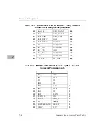
TMCPN710 Transition Module COM1 Connector (J6)
An RJ45 connector is located on the rear panel of the TMCPN710
Transition Module to provide the interface to the COM1 serial port. The
TMCOM1 signal jumper, J7 pins 2 and 3 on the Transition Module, must
be installed to enable COM1 on the Transition Module. The pin
assignments for this connector is as follows:
Table 7-10. TMCPN710 COM1 Connector (J6)
1
DCD
2
RTS
3
GND
4
TXD
5
RXD
6
GND
7
CTS
8
DTR
Содержание MCPN750A
Страница 2: ...MCPN750A CompactPCI Single Board Computer Installation and Use MCPN750A IH5 September 2001 Edition ...
Страница 13: ...xii ...
Страница 15: ...xiv ...
Страница 53: ...1 32 Computer Group Literature Center Web Site Hardware Preparation and Installation 1 ...
Страница 67: ...2 14 Computer Group Literature Center Web Site Startup and Operation 2 ...
Страница 105: ...5 14 Computer Group Literature Center Web Site Remote Start Via the PCI Bus 5 ...
Страница 167: ...7 38 Computer Group Literature Center Web Site Connector Pin Assignments 7 ...
Страница 171: ...A 4 Computer Group Literature Center Web Site Specifications A ...
Страница 187: ...Index IN 10 Computer Group Literature Center Web Site I N D E X ...


