MC9500-K Subsystem
Motorola reserves the right to make changes to any product to
improve reliability, function, or design. Motorola does not assume any
product liability arising out of, or in connection with, the application or
use of any product, circuit, or application described herein. No license
is granted, either expressly or by implication, estoppel, or otherwise
under any patent right or patent, covering or relating to any
combination, system, apparatus, machine, material, method, or
process in which Motorola products might be used. An implied license
exists only for equipment, circuits, and subsystems contained in
Motorola products.
Motorola, Inc.
One Motorola Plaza
Holtsville, New York 11742, USA
1-800-927-9626
http://www.motorola.com/enterprisemobility
MOTOROLA and the Stylized M Logo and Symbol and the
Symbol logo are registered in the U.S. Patent and Trademark
Office. All other product or service names are the property of
their respective owners.
© Motorola, Inc. 2009
72-127014-01 Revision A — August 2009
Installation Guide
Introduction
The MC9500-K contains either a non-WAN
subsystem, an HSPDA WAN subsystem or a CDMA
WAN subsystem. Any of these subsystems can be
removed and replaced with another subsystem.
This guide describes how to remove the subsystem
from an MC9500-K mobile computer and replace it
with a new subsystem.
Hardware
The kit includes:
• Subsystem
• Two keypad screws
• Four subsystem screws
• Connector removal tool.
Required Equipment
The following equipment is required:
• #0 Phillips screwdriver
ESD and Environment Preparation
Follow proper Electro-Static Discharge (ESD)
precautions to avoid damage to the device. Proper
ESD precautions include, but are not limited to,
working on an ESD mat and ensuring that the operator
is properly grounded.
Backing Up Data
Prior to removing the subsystem, backup all MC9500-
K data using ActiveSync. Refer to the
MC9500-K
Mobile Computer Integrator Guide
for more
information.
Remove Existing Subsystem
To remove the existing subsystem:
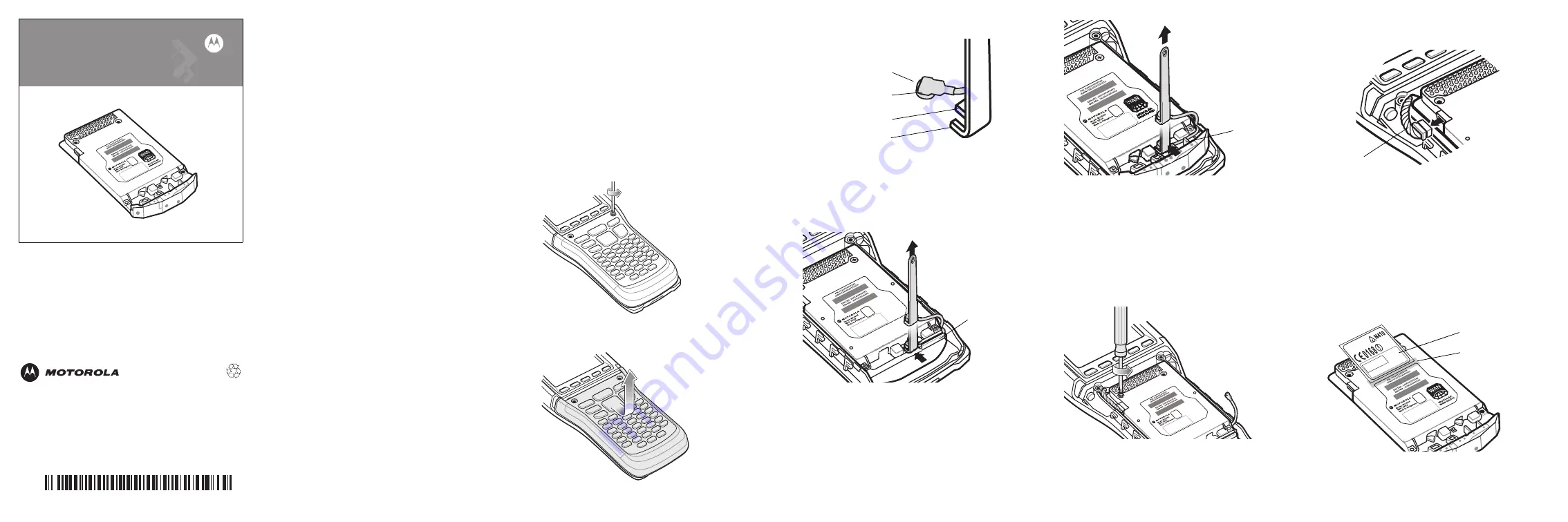
1.
Press the power button to suspend the MC9500-
K.
2.
Wait for red Decode LED to turn on and then turn
off.
3.
Unhook the handstrap.
4.
Remove the battery.
5.
Remove and discard the two screws securing the
keypad.
6.
Slide the keypad down toward the bottom of the
MC9500-K and then lift.
7.
Align the tabs of the removal tool with the RF
cable connector.
8.
Slide the tool over the connector so that the two
lower tabs are below the connector flange and the
upper tab is above the flange.
9.
Lift the removal tool to disconnect the RF cable
connector from the subsystem.
Non-WAN Subsystem
WAN Subsystem
10. On the non-WAN subsystem, carefully remove the
RF cable from the cable channel.
11. On the WAN subsystem, carefully remove the RF
cable from the cable guides.
12. Bend the RF cable away from the subsystem.
13. Remove and discard the four screws securing the
subsystem to the housing.
14. Carefully lift the subsystem from the housing to
access the power harness. Be careful not to pull
on the RF cable.
15. Disconnect the power harness connector from the
subsystem.
16. Lift the subsystem out of the housing.
17. Place the subsystem on an ESD protected area.
Install New Subsystem
To install the new subsystem:
1.
Remove the new subsystem from the ESD
protective bag. Place the old subsystem into this
bag and store for future use.
2.
Remove the subsystem label that is taped to the
new subsystem.
3.
Remove the label backing and place the label in
battery well as shown below.
RF Cable Connector
Connector Flange
Tool Upper Tab
Tool Lower Tab
Cable Channel
Cable Guides
Power Harness
ICES/NMB-003 CLASS B
IC: 109AN-MC9596
NOT FOR USE IN USA
IMEI: XXXXXXXXXXXXX
New Label
Tape


