background image

Using Bluetooth

3 - 3

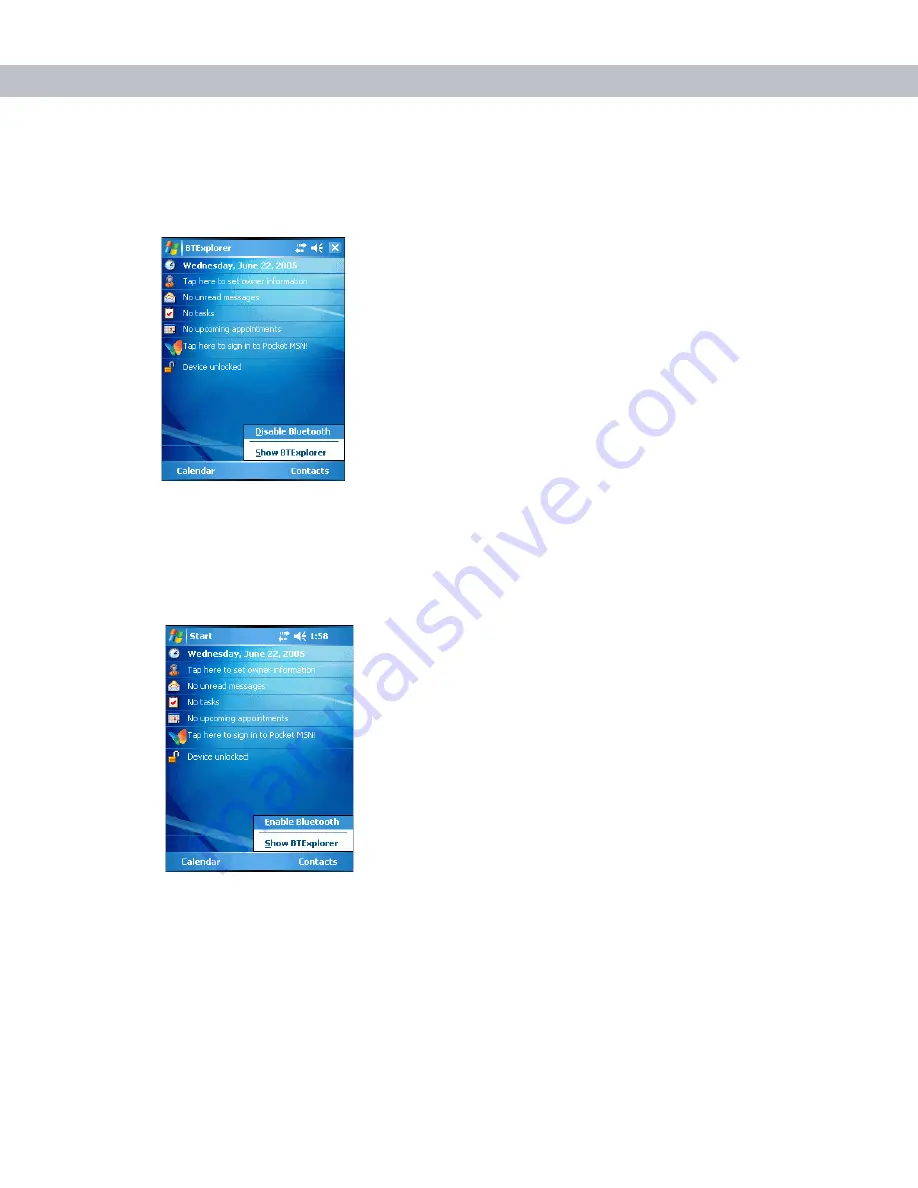
Disabling Bluetooth

To disable Bluetooth, tap 

Bluetooth

 icon - 

Disable Bluetooth

. The 

Bluetooth

 icon changes to indicate that 

Bluetooth is disabled. 

 Figure 3-1    

Disable Bluetooth

Enabling Bluetooth

To enable Bluetooth, tap 

Bluetooth

 icon - 

Enable Bluetooth

. The 

Bluetooth

 icon changes to indicate that 

Bluetooth is enabled.

 Figure 3-2    

Enable Bluetooth

Bluetooth Power States

Cold Boot

Performing a cold boot on the EDA turns off Bluetooth after initialization (which takes a few moments). It is 
normal to see the 

Bluetooth

 icon appear and disappear, as well as a wait cursor, when initialization proceeds in 

all modes.

Содержание MC7090CN

Страница 1: ...MC7090CN Enterprise Digital Assistant User Guide ...

Страница 2: ......

Страница 3: ...MC7090CN User Guide 72E 88965 03 Revision A March 2015 ...

Страница 4: ...user shall not modify merge or incorporate any form or portion of a licensed program with other program material create a derivative work from a licensed program or use a licensed program in a network without written permission from Zebra The user agrees to maintain Zebra s copyright notice on the licensed programs delivered hereunder and to include the same on any authorized copies it makes in wh...

Страница 5: ...n Battery 1 5 Charging the Battery 1 6 Charging the Main Battery and Memory Backup Battery 1 6 Charging Spare Batteries 1 7 Charging Temperature 1 8 Powering On the EDA 1 8 Calibrating the Screen 1 8 Checking Battery Status 1 8 Adjusting the Handstrap 1 8 Removing the Screen Protector 1 10 Battery Management 1 10 Changing the Power Settings 1 11 Changing the Backlight Settings 1 11 Changing the Ke...

Страница 6: ...ng 2 19 Resetting the EDA 2 20 Performing a Warm Boot 2 20 Performing a Cold Boot 2 20 Waking the EDA 2 21 Locking the EDA 2 21 Chapter 3 Using Bluetooth Introduction 3 1 Adaptive Frequency Hopping 3 1 Security 3 2 Turning the Bluetooth Radio Mode On and Off 3 2 Disabling Bluetooth 3 3 Enabling Bluetooth 3 3 Bluetooth Power States 3 3 Cold Boot 3 3 Warm Boot 3 4 Suspend 3 4 Resume 3 4 Modes 3 4 Wi...

Страница 7: ...BEX Object Push Service 3 26 Personal Area Networking Service 3 27 Serial Port Service 3 27 Security Tab 3 28 Discovery Tab 3 29 Virtual COM Port Tab 3 29 Miscellaneous Tab 3 30 Chapter 4 Accessories Introduction 4 1 Cables 4 1 Cradles 4 1 Miscellaneous 4 1 Snap on Modules 4 1 Multi Media Card MMC Secure Digital SD Card 4 2 Single Slot USB Serial Cradle 4 3 Charging the EDA Battery 4 3 Charging th...

Страница 8: ... Scanning 4 13 Using a Cradle 4 14 Cables 4 15 Battery Charging and Operating Power 4 16 LED Charge Indications 4 16 Charging Temperature 4 16 Chapter 5 Maintenance Troubleshooting Introduction 5 1 Maintaining the EDA 5 1 Troubleshooting 5 2 EDA 5 2 Bluetooth Connection 5 4 Single Slot USB Serial Cradle 5 6 Four Slot Ethernet Cradle 5 7 Vehicle Cradle 5 8 Four Slot Spare Battery Charger 5 9 Cables...

Страница 9: ...ws Mobile 5 0 Applications User Guide for Zebra Devices describes how to use Microsoft developed applications Application Guide describes how to use Zebra developed sample applications MC7090CN User Guide describes how to use the MC7090CN EDA MC7090CN Integrator Guide describes how to set up the MC7090CN EDA and accessories SMDK Help File provides API information for writing applications NOTE Scre...

Страница 10: ...ible SD card slot Chapter Descriptions Topics covered in this guide are as follows Chapter 1 Getting Started provides information on getting the EDA up and running for the first time Chapter 2 Using the MC70 provides basic instructions for using the EDA including powering on and resetting the EDA and entering and capturing data Chapter 3 Using Bluetooth explains Bluetooth functionality on the EDA ...

Страница 11: ...A refers to the MC7090CN series of hand held EDAs Italics are used to highlight the following Chapters and sections in this and related documents Dialog box window and screen names Drop down list and list box names Check box and radio button names Icons on a screen Bold text is used to highlight the following Key names on a keypad Button names on a screen bullets indicate Action items Lists of alt...

Страница 12: ...If you have a problem with your equipment contact the Zebra Global Interactive Center for your region Go to http www zebra com support If you purchased your Zebra product from a Zebra Business Partner contact that Business Partner for service Before contacting have the model number and serial number at hand If your problem cannot be solved by the Zebra Global Interactive Center you may need to ret...

Страница 13: ... how to install and charge the batteries replace the strap and power on the EDA for the first time Figure 1 1 MC7090CN Front View Scan Action Button Handstrap Attachment Keypad Numeric Keypad Pictured Power Button I O Connector Up Down Button Touch Screen with Protective Overlay Scan Decode LED Charge Status LED Radio Power Status LED ...

Страница 14: ... battery Battery cover strap assembly Tethered stylus Protective overlay installed on display window Regulatory Guide Quick Start Guide Inspect the equipment for damage If any equipment is missing or damaged contact the Zebra Support Center immediately See page x for contact information Battery Cover Speaker Tether Point Scan Window Imager Model Shown Memory Card Slot Action Button Scan Action But...

Страница 15: ...on Four Slot Ethernet Cradle Charges the EDA main battery and connects the EDA with an Ethernet network VCD7000 Vehicle Cradle Installs in a vehicle and charges the EDA main battery and a spare battery Provides serial data communication between an MC7090CN and an external device Four Slot Spare Battery Charger Charges up to four EDA spare batteries Includes an adapter Belt Mounted Rigid Holster Cl...

Страница 16: ...The standard capacity 1900 mAh battery is shown The extended capacity 3800 mAh battery requires a larger capacity battery cover 1 Insert the battery top first into the battery compartment in the back of the EDA 2 Press the battery down into the battery compartment until the battery release latch snaps into place Figure 1 3 Inserting the Battery Battery Release Latch NOTE Position the battery corre...

Страница 17: ...p through the handstrap slot then tighten and press down to secure Figure 1 5 Inserting the Handstrap The EDA powers up after inserting the battery Removing the Main Battery 1 Press the red Power button to suspend the EDA 2 Loosen the handstrap at the top of the EDA 3 Open the battery cover latches on either side of the battery cover Figure 1 6 Opening the Battery Cover Latches Battery Cover Batte...

Страница 18: ...arge This is also true any time the backup battery is discharged which occurs when the main battery is removed for several hours The backup battery retains RAM data in memory for at least 30 minutes at room temperature when the EDA s main battery is removed When the EDA reaches a very low battery state the combination of main battery and backup battery retains data in memory for at least 40 hours ...

Страница 19: ...ry to ensure proper contact The battery begins charging The amber charge LED on the accessory lights to show the charge status The standard spare battery fully charges in less than four hours and the extended spare battery fully charges in less than eight hours Table 1 2 LED Charge Indicators Charge Status LED Indication Off EDA is not charging EDA is not inserted correctly in the cradle or connec...

Страница 20: ...t these windows also appear upon cold boot Calibrating the Screen To calibrate the screen so the cursor on the touch screen aligns with the tip of the stylus 1 Remove the stylus from its holder on the back of the EDA 2 Carefully press and briefly hold the tip of stylus on the center of each target that appears on the screen 3 Repeat as the target moves around the screen then tap the screen to cont...

Страница 21: ...Getting Started 1 9 2 Secure the handstrap by pressing the two sides together as shown in Figure 1 8 Figure 1 8 Handstrap Adjustment ...

Страница 22: ...ing tips Leave the EDA connected to AC power at all times when not in use Set the EDA to turn off after a short period of non use Set the backlight to turn off after a short period of non use Turn off all wireless activities when not in use Power off the EDA when charging to charge at a faster rate Lift Screen Protector Corner CAUTION Do not use a sharp object to remove the protector Doing so can ...

Страница 23: ...display backlight or use the slider to set a low value for the backlight 5 Select ok Changing the Keypad Backlight Settings To change the keypad backlight settings in order to conserve more battery power 1 Tap Start Settings System tab Keylight icon Battery Power tab 2 Select the On battery power Disable keylight if device if not used for check box and select a value from the drop down list 3 Sele...

Страница 24: ... Turn on flight mode OR Tap the Bluetooth icon and select Disable Bluetooth To turn on the Bluetooth and WAN radios Tap the Connectivity icon and select Turn off flight mode OR Tap the Bluetooth icon and select Enable Bluetooth NOTE The Flight Mode feature only turns off the Bluetooth radios You must turn off the WLAN radio separately ...

Страница 25: ...isted in Table 2 1 Table 2 1 Status Icons Icon Function Description Speaker All sounds are on All sounds are off Vibrate is on Battery Backup battery is very low Main battery is charging Main battery is low Main battery is very low Main battery is full Connectivity Connection is active Synchronization is occurring Time and Next Appointment Displays current time in analog or digital format Multiple...

Страница 26: ...2 Tap and move the slide bar to adjust the volume 3 Select the On or Off radio button to turn the volume on or off You can also adjust the system volume using the Sounds Notifications window or use the Up Down button on the side of the EDA Table 2 2 Task Tray Icons Icon Description Wireless connection status Indicates WLAN signal strength Bluetooth Enabled Bluetooth radio is on Bluetooth Disabled ...

Страница 27: ...el A Battery dialog box also appears indicating the status of the main or backup battery Figure 2 2 Battery Status Dialog Box Also view the battery status using the Power window Connectivity Icon The Connectivity icon indicates the communication status of the EDA when it is connecting to the internet or host computer Figure 2 3 Connectivity Dialog Box ...

Страница 28: ...gure 2 4 Time Icon Format Menu To display current date time and appointments tap the Time icon to display the Time and Next Appointment dialog box Figure 2 5 Time and Next Appointment Dialog Box The dialog box displays the current date and time the battery status and any upcoming appointments in the Calendar Analog Clock Digital Clock Battery Status Icon Upcoming Appointments Current Date and Time...

Страница 29: ... The Scan Decode LED indicates status for scanning The Charge Status LED indicates status for main battery charging The Radio Power Status LED indicates radio status Table 2 3 describes the LED indications Figure 2 7 LED Indicators Multiple Notifications Table 2 3 LED Indications LED State Indication Scan Decode LED Solid Green Successful decode capture Solid Red Laser enabled scanning imaging in ...

Страница 30: ...Figure 2 8 MC70 Numeric Keypad Charge Status LED Slow Blinking Amber Main battery in EDA is charging Solid Amber Main battery in EDA is fully charged Fast Blinking Amber Charging error Off Not charging Radio Power Status LED Slow Blinking Green Any one of the radios is on Off No radio is on The Radio Power Status LED is disabled by default A registry setting change is required to make this LED fun...

Страница 31: ...tion Scroll Up and Down Moves up one item Moves left one item when pressed with the Orange key Scroll Left and Right Moves down one item Moves right one item when pressed with the Orange key Menu Accesses the command or menu above it on the screen Star Produces an asterisk in default state Press and release the blue key then press the Star key to open the Start menu Alphanumeric In default state p...

Страница 32: ...ted item or function Pound Produces a pound number sign Press and release the blue key then press the Pound key to produce an OK Table 2 5 Numeric Keypad Input Modes Key Numeric Mode Orange Key Alpha Lowercase Mode Orange Shift Keys Alpha Uppercase Mode Blue Key SHIFT Key 1st Press 2nd Press 3rd Press 4th Press 1st Press 2nd Press 3rd Press 4th Press 1 1 F1 2 2 F2 a b c A B C 3 3 F3 d e f D E F 4 ...

Страница 33: ...ion Table 2 5 Numeric Keypad Input Modes Continued Key Numeric Mode Orange Key Alpha Lowercase Mode Orange Shift Keys Alpha Uppercase Mode Blue Key SHIFT Key 1st Press 2nd Press 3rd Press 4th Press 1st Press 2nd Press 3rd Press 4th Press Note An application can change the key functions The keypad may not function exactly as described ...

Страница 34: ...igure 2 9 QWERTY Keypad Configuration Table 2 6 QWERTY Keypad Descriptions Key Action Blue Key left Launches applications shown on the keypad in blue Press the Blue key once to activate this mode temporarily followed by another key This displays the following icon at the bottom of the screen until a second key is pressed Press the Blue key twice to lock this mode This displays the following icon a...

Страница 35: ...ft one item when pressed with the Orange key Scroll Down and Right Moves down one item Moves right one item when pressed with the Orange key Menu Accesses the command or menu above it on the screen Shift Changes the state of the alpha characters from lowercase to uppercase Press the Shift key once to activate this mode temporarily followed by another key This displays the following icon at the bot...

Страница 36: ...ng the screen This function is user programmable Menu Use this key in conjunction with the Blue key to instantly display the context menu from any application without tapping the screen This function is user programmable Table 2 7 QWERTY Keypad Input Modes Key Normal Shift Key Orange Key Blue Key Q q Q Start Menu W w W 1 Menu E e E 2 Phone R r R 3 T t T Y y Y _ U u U I i I O o O P p P áü OK A a A ...

Страница 37: ...Shift Shift Z z Z 7 X x X 8 C c C 9 V v V B b B N n N M m M TAB Tab Back tab SPACE Space 0 ENTER Enter Table 2 7 QWERTY Keypad Input Modes Continued Key Normal Shift Key Orange Key Blue Key Note An application can change the key functions The keypad may not function exactly as described ...

Страница 38: ...cter displays To modify an existing character move the cursor to the right of the character then press and hold the Orange key and press the áü key until the special character replaces the original character Table 2 8 lists the special characters you can generate NOTE Special characters are only available on the QWERTY keypad configurations Table 2 8 Special Characters Key Special Characters a A c...

Страница 39: ...Using the MC70 2 15 T u U y Y z Z _ Table 2 8 Special Characters Continued Key Special Characters ...

Страница 40: ...nction See the Microsoft Applications for Mobile and CE 5 0 User Guide to set an application to open Stylus Use the EDA stylus to select items and enter information The stylus functions as a mouse Tap Touch the screen once with the stylus to press option buttons and open menu items Tap and Hold Tap and hold the stylus on an item to see a list of actions available for that item On the pop up menu t...

Страница 41: ...l camera technology to take a digital picture of a bar code stores the resulting image in its memory and executes state of the art software decoding algorithms to extract the data from the image Operational Modes EDAs with an integrated imager support three modes of operation listed below Activate each mode by pulling the trigger or pressing the Scan button Decode Mode In this mode the EDA attempt...

Страница 42: ...y to find the right working range for the bar codes being scanned Angle Scanning angle is important for promoting quick decodes When laser beams reflect directly back into the scanner from the bar code this specular reflection can blind the scanner To avoid this scan the bar code so that the beam does not bounce directly back But don t scan at too sharp an angle the scanner needs to collect scatte...

Страница 43: ...gure 2 14 Imager Scanning 3 Press the scan button The red laser aiming pattern turns on to assist in aiming Ensure the bar code is within the area formed by the brackets in the aiming pattern The Scan Decode LED lights red to indicate that scanning is in process then lights green and a beep sounds by default to indicate the bar code was decoded successfully Note that when the EDA is in Pick List M...

Страница 44: ...in flash memory or a memory card is not lost Perform a warm boot first If the EDA still does not respond perform a cold boot Performing a Warm Boot Hold down the Power button for approximately five seconds As soon as the EDA starts to boot release the Power button Performing a Cold Boot To perform a cold boot simultaneously press the Power button and the 1 and 9 keys Correct Incorrect NOTE Imager ...

Страница 45: ... locked Figure 2 18 Device Locked Unlocked Icons Table 2 9 Wakeup Conditions Default Settings Status Description Conditions for Wakeup Power Off Suspend Mode When the EDA suspends by pressing Power these actions wake the EDA 1 Power button is pressed 2 AC power added or removed 3 Cradle cable connect or disconnect Key or scan button is pressed Real Time Clock set to wake up Auto Off When the EDA s...

Страница 46: ...2 22 MC7090CN User Guide To unlock the device and free it for use tap Unlock Figure 2 19 Unlock Device Window Tap Unlock on the Unlock Device window ...

Страница 47: ...network must be AFH capable in order for AFH to work There is no AFH when connecting and discovering devices Avoid making Bluetooth connections and discoveries during critical 802 11b communications AFH for Bluetooth consists of four main sections Channel Classification A method of detecting an interference on a channel by channel basis or pre defined channel mask Link Management Coordinates and d...

Страница 48: ...no key when a key is requested it is up to user to respond to the key request event Authentication of Bluetooth devices is based upon a challenge response transaction Bluetooth allows for a PIN number or passkey that is used to create other 128 bit keys used for security and encryption The encryption key is derived from the link key used to authenticate the pairing devices Also worthy of note is t...

Страница 49: ...h To enable Bluetooth tap Bluetooth icon Enable Bluetooth The Bluetooth icon changes to indicate that Bluetooth is enabled Figure 3 2 Enable Bluetooth Bluetooth Power States Cold Boot Performing a cold boot on the EDA turns off Bluetooth after initialization which takes a few moments It is normal to see the Bluetooth icon appear and disappear as well as a wait cursor when initialization proceeds i...

Страница 50: ...ard Mode or View Explorer Mode Wizard Mode Wizard Mode provides a simple process for discovering and connecting to Bluetooth devices The following steps provide an example for using the Wizard to connect to remote devices 1 Tap the Bluetooth icon and select Show BTExplorer The BTExplorer window appears 2 Tap File New Connection The New Connection Wizard window appears Figure 3 3 New Connection Wiz...

Страница 51: ...nal Area Network Send or Exchange Objects Associate Serial Port 4 Tap Next The BTExplorer searches for Bluetooth devices in the area and displays the devices in the Select Remote Device window Figure 3 4 Select Remote Device Window 5 Select a device from the list and then tap Next The Connection Favorite Options window appears Figure 3 5 Connection Favorite Options Window NOTE If you select Active...

Страница 52: ...Tap Next The Connection Summary window appears Figure 3 6 Connection Summary Window 9 Tap Connect to connect to the service Explorer Mode The Explorer Mode window is easy to navigate and provides greater control to users familiar with Bluetooth The menu bar provides quick access to the options and tools used to connect to devices To access Explorer Mode tap View Explorer Mode Figure 3 7 Explorer M...

Страница 53: ...avorite for quick access Discovering Bluetooth Device s The EDA can receive information from discovered devices without bonding However once bonded the EDA and a bonded device exchange information automatically when you turn the Bluetooth radio on To find Bluetooth devices in the area 1 Ensure that the Bluetooth device to discover is in discoverable mode 2 Ensure that the two devices are within 30...

Страница 54: ... folder Figure 3 10 Discovered Devices Listed in Untrusted Folder Bonding with Discovered Device s A bond is a relationship created between the EDA and another Bluetooth device in order to exchange information in a secure manner Creating a bond involves entering the same PIN on the two devices After creating a bond and turning on the Bluetooth radios the devices recognize the bond and can exchange...

Страница 55: ...Untrusted Devices folder tap and hold on a device to pair with Figure 3 11 Pairing a Remote Device 3 Select Pair from the pop up menu The PIN Code Request window appears Figure 3 12 PIN Code Request Window 4 In the PIN Code text box enter the PIN number between 1 and 16 characters and then tap OK 5 On the remote device enter the same PIN number ...

Страница 56: ...the device name moves to the Trusted Devices folder Figure 3 13 Bonded Paired Discovered Device Renaming a Bonded Device To rename a bonded device 1 Launch BTExplorer 2 Tap and hold the device to rename Figure 3 14 Rename Device Selection Dialog Box ...

Страница 57: ... Device Name Window 4 Enter a new name for the bonded device in the text box Tap OK Deleting a Bonded Device To delete a device no longer needed 1 Launch BTExplorer 2 Tap and hold the device to delete and select Delete in the pop up menu Figure 3 16 Deleting a Bonded Device 3 A confirmation dialog appears Tap Yes ...

Страница 58: ...on the device requesting the bond The PIN must be between 1 and 16 characters 3 In the Device Name text box edit the name of the device requesting the bond if desired 4 Tap OK to create the bond The EDA can now exchange information with the other device Discovering Services Before using services first discover remote devices and then bond to those devices To determine what services are available o...

Страница 59: ...fer Services To transfer files between the EDA and another Bluetooth enabled device 1 Ensure the EDA is discoverable and connectable See Bluetooth Settings on page 3 24 2 Discover and bond pair with the remote access point See Bonding with Discovered Device s on page 3 8 3 In BTExplorer select the Remote Devices folder 4 Select the Trusted Devices folder 5 Tap the remote device folder 6 Tap and ho...

Страница 60: ...ate a new folder or file on the remote device 1 Tap and hold on the file and select New Folder or New File The Create New Folder or Create New File window appears 2 Enter the name for the new folder or file 3 Tap OK to create the new folder or file on the remote device Deleting a File To delete a file from the remote device 1 Tap and hold on the file and select Delete 2 In the Delete Remote Device...

Страница 61: ...op up menu 7 Tap and hold LAN Access using PPP service and select Connect from the pop up menu The EDA connects with the access point 8 Tap Start Internet Explorer The Internet Explorer window appears 9 In the address field enter an internet address and tap the Enter button The web page loads Dial Up Networking Services To use a phone that has Bluetooth capabilities as a modem for the EDA create a...

Страница 62: ...mote Devices folder 4 Select the Trusted Devices folder 5 Tap the remote device folder 6 Tap and hold on Dial up Networking and select Connect from the pop up menu The Select Dial up Networking Entry window appears Figure 3 21 Select Dial up Networking Entry Window 7 Select a dial up entry 8 Tap OK The EDA begins to communicate with the phone If required the phone requests permission to communicat...

Страница 63: ...assword for this connection 12 In the Domain text box enter the domain for this connection if required 13 Tap OK The phone begins dialing then connects to the network Figure 3 23 Connecting to Bluetooth Phone 14 To end a session tap the Connection icon and then tap Disconnect in the dialog box Figure 3 24 Connectivity Dialog Box ...

Страница 64: ...he pop up menu Figure 3 25 Add Dial Up Entry The Add Phone Book Entry window appears 2 In the Name for the connection text box enter a name for this connection 3 In the Country Code text box enter the country code for the country that you are calling 4 In the Area Code text box enter the area code 5 In the Phone Number text box enter the phone number 6 Tap OK ...

Страница 65: ...ct Push and select Connect The OBEX Object Push window appears 7 In the Action drop down list select one of the following options Send Contact Information Swap Contact Information Fetch Contact Information or Send a Picture Sending a Contact To send a contact to another device 1 Ensure the EDA is discoverable and connectable See Bluetooth Settings on page 3 24 2 Discover and bond pair with the rem...

Страница 66: ... dialog box on the other device to accept the contact A Send Contact dialog appears 12 Tap Ok Sending a Picture To send a picture to another device 1 Ensure the EDA is discoverable and connectable See Bluetooth Settings on page 3 24 2 Discover and bond pair with the remote device See Bonding with Discovered Device s on page 3 8 3 In BTExplorer select the Remote Devices folder 4 Select the Trusted ...

Страница 67: ...he other device 10 Tap Open 11 Tap OK to send the picture to the other device and display a confirmation dialog box on the other device to accept the picture A Send Picture dialog appears 12 Tap Ok Serial Port Services Use the wireless Bluetooth serial port connection as you would a physical serial cable connection Configure the application that will use the connection to the correct serial port T...

Страница 68: ...ync just as you would a physical serial cable connection You must configure the application that will use the connection to the correct serial port To establish an ActiveSync connection 1 On the host computer ensure the Bluetooth software is set up properly 2 Ensure the mobile computer is discoverable and connectable See Bluetooth Settings on page 3 24 3 Discover and bond pair with the remote devi...

Страница 69: ...c initates Personal Area Network Services Connect two or more Bluetooth devices to share files collaborate or play multi player games To establish a Personal Area Network connection 1 Ensure the EDA is discoverable and connectable See Bluetooth Settings on page 3 24 2 Discover and bond pair with the remote device See Bonding with Discovered Device s on page 3 8 3 In BTExplorer select the Remote De...

Страница 70: ... to configure the EDA s Bluetooth connection modes Figure 3 33 BTExplorer Settings Device Info Tab Services Tab Use the Services tab to add or delete Bluetooth services Figure 3 34 BTExplorer Settings Services Tab Device Name Displays the name of the EDA Discoverable Mode Select whether or not the EDA is discoverable by other Bluetooth devices Connectable Mode Select whether or not the EDA is conn...

Страница 71: ...following sections for information on the available services Dial Up Networking Service Dial up Networking allows other Bluetooth devices to access a dial up modem Figure 3 36 Add Local Service Window Service Name Displays the name of the service Service Security Select the type of security from the drop down list Options are None Authenticate or Authenticate Encrypt Local COM Port Select the COM ...

Страница 72: ...Name Displays the name of the service Service Security Select the type of security from the drop down list Options are None Authenticate or Authenticate Encrypt Root Directory Select the directory that other Bluetooth devices can access File Permissions Select the file permissions for the selected directory Check the appropriate box to grant read access write access and delete access Service Name ...

Страница 73: ...vices to access COM ports Figure 3 40 Serial Port Service Window Do not allow clients to push objects Disables clients from pushing objects to the EDA Inbox Directory Select a directory where another Bluetooth device can store files Service Name Displays the name of the service Service Security Select the type of security from the drop down list Options are None Authenticate or Authenticate Encryp...

Страница 74: ... Options are None Authenticate or Authenticate Encrypt Local COM Port Select the COM port Local Baud Rate Select the communication baud rate Local Port Options Select the port option Use PIN Code Incoming Connection Select for automatic use of the PIN code entered in the PIN Code text box It is recommended not to use this automatic PIN code feature See Security on page 3 2 for more information PIN...

Страница 75: ...luetooth communication Figure 3 43 BTExplorer Settings Virtual COM Port Tab Inquiry Length Sets the amount of time the EDA takes to discover Bluetooth devices in the area Name Discovery Mode Select either Automatic or Manual Discovered Devices Deletes all discovered devices and link keys COM4 Bluetooth Enable or disable COM Port 4 COM5 Bluetooth Enable or disable COM Port 5 COM9 Bluetooth Enable o...

Страница 76: ...ction type to highlight when connected In the Wizard Mode the only options are Favorites or None In the Explorer Mode the options are None Tree View Only List View Only or Tree and List View Apply Text Style Select the text style to apply to the connection text Apply Text Color Select the text color to apply to the connection text ...

Страница 77: ...hronizes the EDA with a host computer through a USB connection Four Slot Ethernet cradle charges the EDA main battery and connects the EDA with an Ethernet network Vehicle cradle charges the EDA main battery and a spare battery Miscellaneous Four Slot Spare Battery Charger charges up to four EDA spare batteries Multimedia Card or Secure Digital SD Card provides secondary non volatile storage Belt ...

Страница 78: ...rt the card with the card contacts facing down and the cut corner on the right until you feel a click 4 Replace the housing cover and secure with the screws To remove an MMC SD card 1 Power off the EDA 2 Remove the card cover at the top of the EDA by loosening the screws and lifting the cover out of the slot 3 Using the stylus press and release the card to eject it 4 Remove the card from the card ...

Страница 79: ... Connect the cradle to power Insert the EDA into the EDA slot to begin charging Figure 4 2 EDA Battery Charging NOTE Use only an approved power supply output rated 12 Vdc and minimum 3 33A The power supply is certified to EN60950 with SELV outputs Use of an alternative power supply will invalidate any approval given to this device and may be dangerous HINWEIS Benutzen Sie nur eine von genehmigte S...

Страница 80: ...teries in temperatures from 0o C to 40o C 32 F to 104 F Note that at temperatures above 35o C charging is intelligently controlled by the EDA and the charging accessory in order to ensure safe operation and optimize long term battery life To accomplish this for small periods of time the EDA or accessory alternately enables and disables battery charging to keep the battery at acceptable temperature...

Страница 81: ...age 1 7 for charging status indications The standard battery fully charges in approximately four hours and the extended capacity battery fully charges in approximately eight hours NOTE Use only an approved power supply output rated 12 Vdc and minimum 9A The power supply is certified to EN60950 with SELV outputs Use of an alternative power supply will invalidate any approval given to this device an...

Страница 82: ... the EDA For cradle installation and communication setup procedures refer to the MC7090CN Integrator Guide Once installed in a vehicle the cradle holds the EDA securely in place provides power for operating the EDA provides a serial port for data communication between an EDA and an external device e g a printer re charges the battery in the EDA re charges a standard capacity or extended capacity s...

Страница 83: ... battery to begin charging 1 Lift the battery release lever Figure 4 7 Inserting the Spare Battery 2 Insert the spare battery in the spare battery charging slot in the cradle with the charging contacts facing up and to the rear of the cradle 3 Release the battery release lever The battery release lever locks the spare battery into place Release Lever Extended Capacity Battery Shown Battery Release...

Страница 84: ... Temperature Charge batteries in temperatures from 0o C to 40o C 32 F to 104 F Note that at temperatures above 35o C charging is intelligently controlled by the EDA and the charging accessory in order to ensure safe operation and optimize long term battery life To accomplish this for small periods of time the EDA or accessory alternately enables and disables battery charging to keep the battery at...

Страница 85: ...pply is certified to EN60950 with SELV outputs Use of an alternative power supply will invalidate any approval given to this device and may be dangerous HINWEIS Benutzen Sie nur eine von genehmigte Stromversorgung mit einer Ausgangsleistung von 12 V Gleichstrom und mindestens 3 33A Die Stromversorgung ist nach EN60950 für die Verwendung in SELV Stromkreisen zertifiziert Bei Verwendung eines andere...

Страница 86: ...ately 2 5 hours and the extended capacity battery fully charges in approximately six hours Charging Temperature Charge batteries in temperatures from 0o C to 40o C 32 F to 104 F Note that at temperatures above 35o C charging is intelligently controlled by the charger in order to ensure safe operation and optimize long term battery life To accomplish this for small periods of time the charger alter...

Страница 87: ... the MSR onto the bottom of the EDA and secure by snapping the arms into the EDA housing Figure 4 11 MSR Installation To remove the MSR open the arms and pull the MSR from the EDA Table 4 3 Spare Battery LED Charging Indicators LED Indication Off No spare battery in slot battery is not charging battery is not inserted correctly in the charger charger is not powered Slow Blinking Amber Spare batter...

Страница 88: ...tripe on the card facing down Swipe the card in either direction from left to right or from right to left For best results gently press down on the card while swiping to ensure contact with the bottom of the reader Figure 4 12 Magnetic Stripe Card Swiping TRG7000 Trigger Handle The TRG7000 Trigger Handle pistol grip accessory adds a gun style handle with a scanning trigger to the EDA It increases ...

Страница 89: ...e release secures the EDA to the Trigger Handle Figure 4 13 Inserting the EDA into the Trigger Handle Removing the EDA To remove the EDA press the release down and pull the EDA forward Figure 4 14 Removing the EDA Scanning To scan bar codes 1 Start the EDA s scanning application 2 Aim the EDA at the bar code Release Release ...

Страница 90: ... charge the EDA s battery while the EDA is in the Trigger Handle insert the EDA into either the Single Slot USB Serial cradle or the Four Slot Ethernet cradle Figure 4 16 Inserting the EDA Into the Cradle for Charging CAUTION Do not place a Trigger Handle with an attachment such as a Magnetic Stripe Reader MSR into a cradle Remove the attachment before inserting the Trigger Handle into the cradle ...

Страница 91: ... Cables Communication charge cables Provide the EDA with operating and charging power when used with the approved power supply Synchronize information between the EDA and a host computer With customized or third party software it can also synchronize the EDA with corporate databases Provide serial connection through the serial pass through port for communication with a serial device such as a host...

Страница 92: ...charging status indications 3 When charging is complete remove the cable by gently pulling the EDA and the cable apart LED Charge Indications The amber Charge LED on the EDA indicates battery charging status See Table 1 2 on page 1 7 for charging status indications Charging Temperature Charge batteries in temperatures from 0oC to 40oC 32 F to 104 F Note that at temperatures above 35oC charging is ...

Страница 93: ...ong impact Protect the EDA from temperature extremes Do not leave it on the dashboard of a car on a hot day and keep it away from heat sources Do not store or use the EDA in any location that is dusty damp or wet Use a soft lens cloth to clean the EDA If the surface of the EDA screen becomes soiled clean it with a soft cloth moistened with a diluted window cleaning solution Periodically replace th...

Страница 94: ...on page 2 20 EDA removed from cradle while battery was charging Insert EDA in cradle The standard capacity battery 1900 mAh fully charges in less than four hours The extended capacity battery 3800 mAh fully charges in less than eight hours Cannot see characters on display EDA not powered on Press the Power button During data communication no data transmitted or transmitted data was incomplete EDA ...

Страница 95: ...ated correctly Re calibrate the screen See Calibrating the Screen on page 1 8 The system is not responding Warm boot the system See Resetting the EDA on page 2 20 A message appears stating that the EDA memory is full Too many files stored on the EDA Delete unused memos and records If necessary save these records on the host computer or use an SD card for additional memory Too many applications ins...

Страница 96: ...ndition notification Note If the scanner is still not reading symbols contact the distributor or Zebra Table 5 1 Troubleshooting the EDA Continued Problem Cause Solution Table 5 2 Troubleshooting Bluetooth Connection Problem Cause Solution EDA cannot find any Bluetooth devices nearby Too far from other Bluetooth devices Move closer to the other Bluetooth device s within a range of 10 meters The Bl...

Страница 97: ... should close open Bluetooth sessions and reopen them This reestablishes the piconet lost during the suspend My application created a successful RFCOMM session with another Bluetooth device but the session was dropped Device went out of range or was shut off Check the return value of APIs for errors Look for a DCD state change event in the Microsoft Bluetooth stack DCD window of the Bluetooth conn...

Страница 98: ... Verify that other batteries charge properly If so replace the faulty battery The EDA is not fully seated in the cradle Remove and re insert the EDA into the cradle ensuring it is firmly seated Ambient temperature of the cradle is too warm Move the cradle to an area where the ambient temperature is between 0o C and 35o C Spare battery is not charging Battery not fully seated in charging slot Remov...

Страница 99: ...tion Incorrect cable configuration Ensure the correct cable Ethernet is used with the cradle Communication software improperly configured Perform setup as described in the MC70 Integrator Guide EDA ActiveSync disabled or not configured to accept network connection On the EDA tap Start ActiveSync Tools Options Options button Then uncheck the Enable PC sync using this connection check box Host Activ...

Страница 100: ...up Cradle is not receiving power Ensure the power input cable is securely connected to the cradle s power port EDA battery is not recharging EDA was removed from the cradle too soon Replace the EDA in the cradle The standard capacity battery 1900 mAh fully charges in less than four hours The extended capacity battery 3800 mAh fully charges in less than eight hours Battery is faulty Replace the bat...

Страница 101: ... power supply The standard capacity battery 1900 mAh fully charges in less than four hours The extended capacity battery 3800 mAh fully charges in less than eight hours Battery is faulty Verify that other batteries charge properly If so replace the faulty battery Battery contacts not connected to charger Verify that the battery is seated in the battery well correctly with the contacts facing down ...

Страница 102: ...e power cable to the EDA ensuring it is firmly connected During data communication no data transmits or transmitted data was incomplete Cable was disconnected from EDA during communications Re attach the cable and retransmit Incorrect cable configuration See the system administrator Communication software is not installed or configured properly Perform setup as described in the MC7090CN Integrator...

Страница 103: ... incomplete EDA detached from MSR during communications Reattach EDA to MSR and retransmit Incorrect cable configuration See the system administrator Communication software is not installed or configured properly Perform setup as described in the MC7090CN Integrator Guide Table 5 9 Troubleshooting the Trigger Handle Problem Cause Solution Cannot insert EDA in Trigger Handle Cleat is not installed ...

Страница 104: ...ower connections to the cradle are connected properly Cannot print to printer Printer cable not connected properly Ensure cable is connected properly to the printer and Trigger Handle EDA does not wake from suspend mode when trigger is pressed The trigger only wakes the EDA from the suspend mode if a scanning application is active Press a key on the EDA to wake from the suspend mode Table 5 9 Trou...

Страница 105: ...ze Touch Panel Glass analog resistive touch Backlight LED backlight Main Battery Rechargeable Lithium Ion 3 7V 1900 mAh Smart Battery Extended Cap Battery Optional 3 7V 3800 mAh Smart Battery Backup Battery NiMH battery rechargeable 20mAh 1 2V not user accessible Expansion Slot User accessible SDIO slot with secure cover accommodates extended cards with cover removed Network Connections Ethernet v...

Страница 106: ... Operating Channels Chan 8 169 5040 5845 MHz 4920 4980 MHz Japan only Chan 1 13 2412 2472 MHz Chan 14 2484 MHz Japan only Actual operating frequencies depend on regulatory rules and certification agency Security WPA WEP 40 or 128 bit TKIP TLS TTLS MS CHAP TTLS MS CHAP v2 TTLS CHAP TTLS MD5 TTLS PAP PEAP TLS PEAP MS CHAP v2 AES LEAP Spreading Technique Direct Sequence Spread Spectrum DSSS and Ortho...

Страница 107: ... Vertical 24 5 Optical Resolution 640 H x 480 V pixels gray scale Roll 360 Pitch Angle 60 from normal Skew Tolerance 50 from normal Ambient Light Total darkness to 9 000 ft candles 96 900 Lux Shock 2 000 5 G Focal Distance from Front of Engine Near 5 inches Far 9 inches Aiming Element VLD 650 nm 5 nm Illumination Element LED 635 nm 20 nm Table A 1 EDA Technical Specifications Continued Item Descri...

Страница 108: ...ensing Drop 30 0 in 76 2 cm drops to vinyl tiled concrete at room temperature Electrostatic Discharge ESD 15 kV air 8 kV contact Table A 3 Four Slot Ethernet Cradle Technical Specifications Feature Description Dimensions 5 40 in H x 18 25 in W x 4 38 in D 13 72 cm H x 46 36 cm W x 11 13 cm D Weight 2 38 lb 1079 g Power 12 V Interface Ethernet Operating Temperature 32 to 122 F 0 to 50 C Storage Tem...

Страница 109: ...V air 8 kV contact Table A 5 Magstripe Reader MSR Technical Specifications Feature Description Dimensions 3 1 in L x 3 3 in W x 1 4 in H 7 87 cm L x 8 38 cm W x 3 56 cm H Weight 1 7 oz 48 g Interface Serial with baud rate up to 19 200 Format ANSI ISO AAMVA CA DMV user configurable generic format Swipe Speed 5 to 50 in 127 to 1270 mm sec bi directional Decoders Generic Raw Data Mode Buffered unbuff...

Страница 110: ...A 6 MC7090CN User Guide ...

Страница 111: ...ting 128 letters numerals punctuation marks and control characters It is a standard data transmission code in the U S Autodiscrimination The ability of an interface controller to determine the code type of a scanned bar code After this determination is made the information content is decoded B Bar The dark element in a printed bar code symbol Bar Code A pattern of variable width bars and spaces wh...

Страница 112: ...ealth A federal agency responsible for regulating laser product safety This agency specifies various laser operation classes based on power output during operation CDRH Class 1 This is the lowest power CDRH laser classification This class is considered intrinsically safe even if all laser output were directed into the eye s pupil There are no special operating procedures for this class CDRH Class ...

Страница 113: ... and for communicating with a host computer and provides a storage place for the terminal when not in use D Data Communications Equipment DCE A device such as a modem which is designed to attach directly to a DTE Data Terminal Equipment device DCE See Data Communications Equipment DCP See Device Configuration Package Dead Zone An area within a scanner s field of view in which specular reflection m...

Страница 114: ...ly in retail Element Generic term for a bar or space Encoded Area Total linear dimension occupied by all characters of a code pattern including start stop characters and data ENQ RS 232 ENQ software handshaking is also supported for the data sent to the host ESD Electro Static Discharge F File Transfer Protocol FTP A TCP IP application protocol governing file transfer via network or telephone line...

Страница 115: ...s in a discrete code Interleaved Bar Code A bar code in which characters are paired together using bars to represent the first character and the intervening spaces to represent the second Internet Protocol Address See IP IOCTL Input Output Control I O Ports interface The connection between two devices defined by common physical characteristics signal characteristics and signal meanings Types of in...

Страница 116: ...Display LED Indicator A semiconductor diode LED Light Emitting Diode used as an indicator often in digital displays The semiconductor uses applied voltage to produce light of a certain frequency determined by the semiconductor s particular chemical composition Light Emitting Diode See LED Liquid Crystal Display LCD A display that uses liquid crystal sealed between two glass plates The crystals are...

Страница 117: ...erstanding and translating any network information or request sent by any other ODI compatible protocol into something a NetWare client can understand and process Open System Authentication Open System authentication is a null authentication algorithm P PAN Personal area network Using Bluetooth wireless technology PANs enable devices to communicate wirelessly Generally a wireless PAN consists of a...

Страница 118: ...cedes the start character of a bar code symbol and follows the stop character QWERTY A standard keyboard commonly used on North American and some European PC keyboards QWERTY refers to the arrangement of keys on the left side of the third row of keys R RAM Random Access Memory Data in RAM can be accessed in random order and quickly written and read Reflectance Amount of light returned from an illu...

Страница 119: ...vices to distinguish between the home and roaming service SMDK Symbol Mobility Developer s Kit Soft Reset See Warm Boot Space The lighter element of a bar code formed by the background between bars Specular Reflection The mirror like direct reflection of light from a surface which can cause difficulty decoding a bar code Start Stop Character A pattern of bars and spaces that provides the scanner w...

Страница 120: ...es to be sent to multiple networks within an organization or around the world hence its use in the worldwide Internet Every client and server in a TCP IP network requires an IP address which is either permanently assigned or dynamically assigned at startup Telnet A terminal emulation protocol commonly used on the Internet and TCP IP based networks It allows a user at a terminal or computer to log ...

Страница 121: ...required packet sequence checking and error notification must be written into the applications UPC Universal Product Code A relatively complex numeric symbology Each character consists of two bars and two spaces each of which is any of four widths The standard symbology for retail food packages in the United States V Visible Laser Diode VLD A solid state device which produces visible laser light W...

Страница 122: ...Glossary 12 MC7090CN User Guide ...

Страница 123: ...e 1 3 vehicle cradle 1 3 4 1 4 6 wall mounting kit cradle 1 3 action button 2 16 ActiveSync icon 2 2 adaptive frequency hopping 3 1 adjusting handstrap 1 8 adjusting volume 2 2 AFH 3 1 auto charge cable 1 3 4 15 B backup battery charging 1 6 bar codes one dimensional 2 17 two dimensional 2 17 battery charging 1 6 4 3 4 5 4 6 4 10 check status 1 8 installing 1 4 removing 1 5 battery chargers commun...

Страница 124: ...icators 4 16 configuration 1 4 connectivity icon 2 1 2 3 conventions notational ix cradles four slot Ethernet 1 3 4 1 4 5 four slot spare battery charger 4 1 4 9 single slot USB serial 4 1 4 3 vehicle 1 3 4 1 4 6 D data capture imager operational modes decode mode 2 17 image capture mode 2 18 pick list mode 2 17 imaging 2 17 linear scanning 2 17 one dimensional bar codes 2 17 scan angle 2 18 scan ...

Страница 125: ...lling 1 4 maintenance 5 1 MMC 1 3 4 1 4 2 modem cable 1 3 4 15 MSR 1 3 4 1 4 11 installation 4 11 magnetic stripe reading 4 12 multi media card 1 3 4 1 4 2 N navigation bar 2 1 icons 2 1 notational conventions ix numeric keypad 2 6 input modes 2 8 key descriptions 2 7 O O Neil printer cable 4 15 operating environment A 1 P power button 1 8 2 16 2 20 printer cable 1 3 Q QWERTY keypad 2 10 input mod...

Страница 126: ...aker 2 1 2 2 time and appointment 2 1 2 4 strap 1 2 stylus 1 2 1 3 2 16 suspend 1 5 2 16 3 4 Symbol mobility developer kit x 1 3 T task tray icons 2 2 technical specifications A 1 accessories A 4 temperature A 2 charging 1 8 4 4 time and appointment icon 2 1 2 4 TRG7000 4 1 trigger handle 4 1 4 12 troubleshooting 5 2 U unpacking 1 2 up and down button 2 16 USB charger 1 3 USB client charge cable 4...

Страница 127: ...___________________________________________________________________________ _____________________________________________________________________________________ What topics need to be added to the index if applicable _____________________________________________________________________________________ _____________________________________________________________________________________ What topic...

Страница 128: ......

Страница 129: ......

Страница 130: ... Lincolnshire IL U S A http www zebra com Zebra and the stylized Zebra head are trademarks of ZIH Corp registered in many jurisdictions worldwide All other trademarks are the property of their respective owners 2015 ZIH Corp and or its affiliates All rights reserved ...

Отзывы: