


6-1
CHAPTER 6
Cable Suppression Cores
The Suppression Cores are used to reduce Radiated Emissions generated by I/O and
power connections and to protect against electrical fast transient events such as ESD
and Spikes. The use of the Suppression Cores is required for all I/O wires (per module)
and all radio communication cables to comply with 89 / 336 EEC and FCC Part 15
Directives.
Assembly Instructions:
1. Twist all Input and Output wires together (per module) for easy insertion into one
ferrite as shown in Figure
2. Clamp one ferrite on all Input and Output wires (per module) as shown in Figure
3. Each ferrite is to be placed as close as possible to the mating connector plug. The
ferrite should not exceed a distance of 10.0 cm from the module itself.
4. Clamp a ferrite on the CPU Port 2 communication cable as close to the radio as
possible as shown in and Figure
5. Clamp a ferrite on the CPU Port 3 communication cable as close to the CPU Port 3
connector as possible as shown in Figure
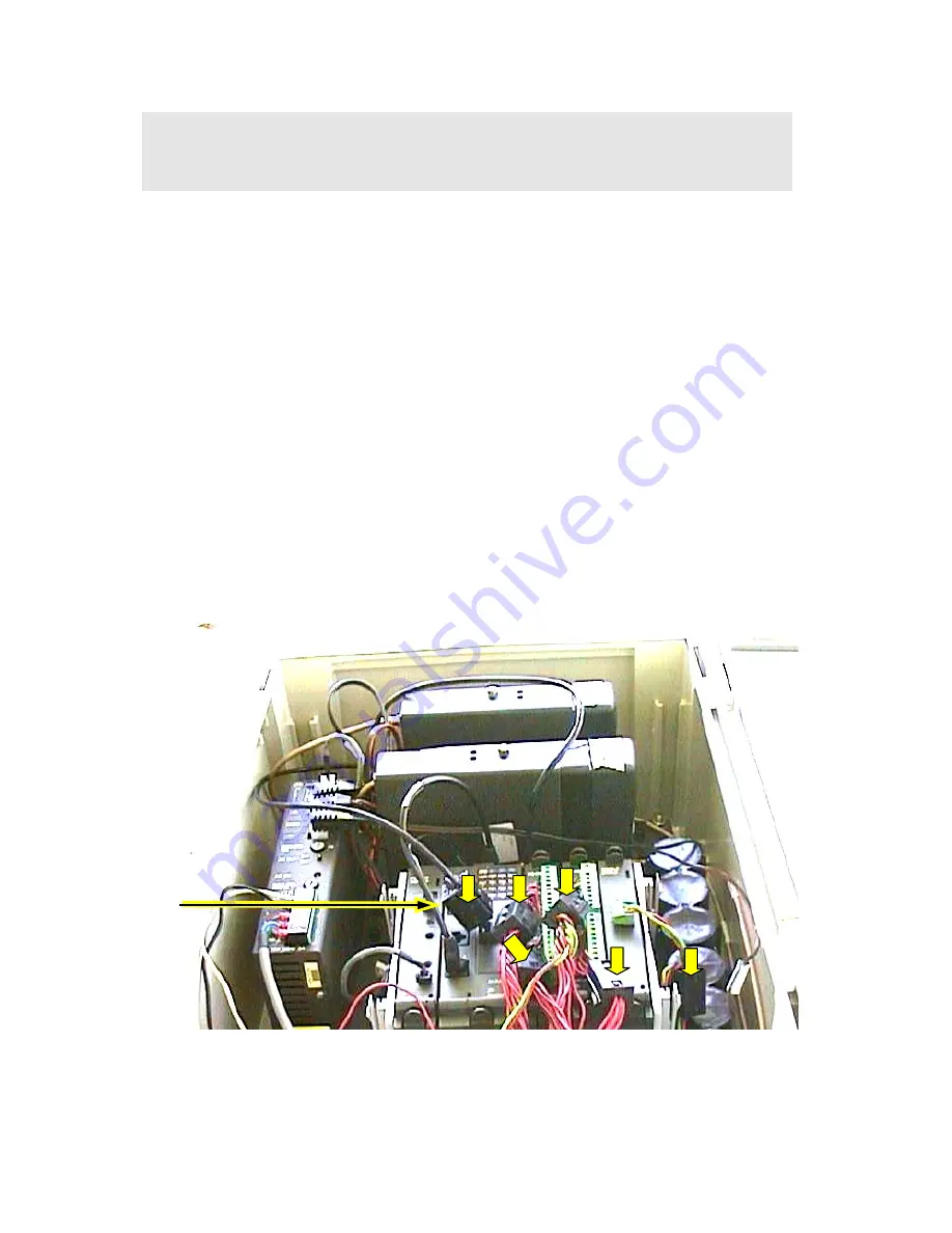
Figure
6-1 I/O and CPU Port 3 Cable Suppression Cores – User Connections
Ferrite Units
1
2
3
5
6
4
StockCheck.com