3-2
3.1.3
Front Panel - Controls, Indicators and Connectors
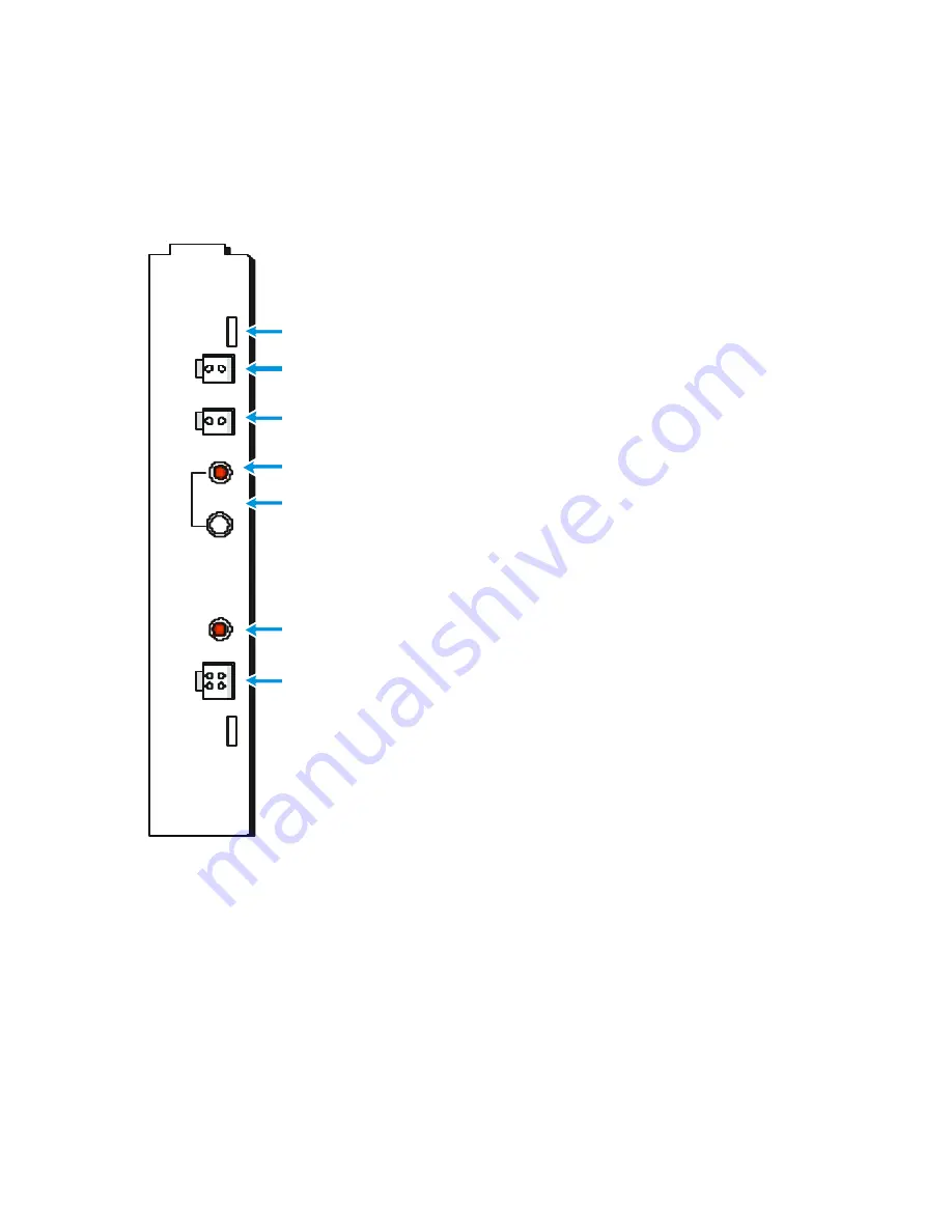
The front panel controls, indicators and connectors of the Power Supply Module are
described in Figure
P O W E R
S U PP LY
B AT
A U X
D C
O N
O F F
P W R
P W R
IN
B AT - C o n n ec to r. U se d fo r i n te rc on n ec ti n g 1 2 V D C
p o w e r be tw e en the Po w e r S u p pl y mo d ul e an d th e ba tte ry
R e p la ce a bl e fu s es l oc a ted in si d e p an e l
A U X - D C o u tp u t c o nn ec to r.
S u p pl ie s 1 2 V D C p o we r to P o rta bl e R a di o
D C O N /O F F - S w i tc h. C o ntro ls the D C
o u tp u t o f th e P o w e r S u pp l y mo d ul e
In d ic a ti o n L ED . L i t w h e n th e P o w e r S u pp l y rec ei ve s val id in p u t V ol tag e
P o w e r In C on n ec to r
F K N 4 46 3 c a bl e - T o 4 5 VA P o w e r T ran s fo rm e r
F K N 4 46 9 c a bl e - 1 2 - 1 6 V D C
In d ic a ti o n L ED – L i t w h e n P o we r S up p l y Mo du l e o u tpu ts D C V ol ta ge
Figure
3-1 Power Supply Module – Front Panel
StockCheck.com


