3-8
MAINTENANCE
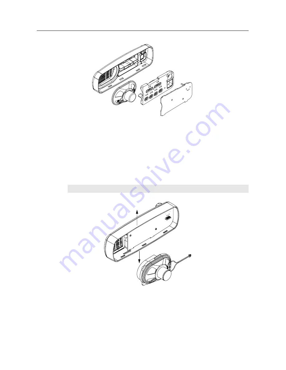
Figure 3-8 Board, Keypad and Speaker Removal
6.
Remove the speaker from the control head housing.
6.5
Disassembly of Control Heads - GM360 and GM380 (with display)
1.
Dismount the control head housing from the back housing as described for control heads
without displays, Figure 3-6 and 3-7.
2.
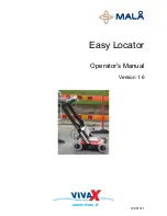
On the GM360, disconnect the speaker socket and pull out the speaker (with speaker tube)
by stretching the control head housing, Figure 3-9.
Figure 3-9 Speaker and Speaker Tube Removal
3.
Remove the board from the control head housing by stretching the control head housing and
pulling up on the board.
4.
Remove the keypad from the control head housing by lifting up the rubber keypad.
NOTE
The speaker and speaker tube are glued together to form one unit. (GM360 only)
ZWG0130216-O
ZWG0130218-O
Содержание GM140
Страница 1: ...Professional Radio GM300 Series Basic Service Manual 68P64115B51 Issue July 2000 ...
Страница 16: ...2 6 MODEL CHART AND TEST SPECIFICATION ...
Страница 44: ...5 4 RADIO TUNING AND PROGRAMMING ...
Страница 46: ...6 2 POWER UP SELF TEST ...


