


MODEL:
FOCUS 72
FOCUS 72-2
FOCUS 72-3
FOCUS 72-4
FOCUS 72-W
FOCUS 72-W2
FOCUS 72-W3
FOCUS 72-W4
EU EN
QUICK START GUIDE
For a full explanation of all features and instructions, please refer to the User’s Guide.
(available for download from www.motorolastore.com).
1. How to register your Camera to Hubble account
A. Setting Up the Camera - can be connected via WiFi or LAN
Via WIFI
Step 1: Connect the antenna with the connector on the rear surface of
the camera
.
Step 2: Insert the power adapter connector into the camera's power
socket and screw in the waterproof cover. Connect the power
adaptor plug to a suitable mains socket and wait for the LED to
start blinking RED.
Step 3: Press and hold the pair button for 3 seconds or more until both
RED and GREEN LEDs blink together.
Step 4: From the APP, press "+" camera to search for the Focus72, then
follow the instructions from the APP.
Via LAN
Step 1: Connect the LAN cable to the camera's LAN socket and the
other end to your router, and screw in the waterproof cover.
If the LAN is not being connected, fit the waterproof blanking
cap provided.
Step 2: Insert the power adapter connector into the camera's power
socket and screw in the waterproof cover. Connect the power
adaptor plug to a suitable mains socket and wait for the LED to
start blinking RED.
Step 3: Press and hold the pair button for 3 seconds or more until both
RED and GREEN LEDs blink together.
Step 4 : From the APP, press "+" camera to search for the Focus72, then
follow the instructions from the APP.
3
2
1
Pair button
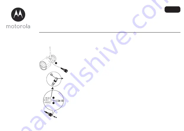
B. How to assemble the waterproof plug for the LAN cable
Step 2: Pass the LAN plug and cable through
Part 1, the Rubber Gasket and Part 2 in the order
shown below.
Step 1: Place the O-Ring washer over the end of
the LAN socket.
Step 3: Connect the LAN plug into the LAN
socket.
Step 4: Turn and lock Part 2 to the LAN socket.
Step 5: Make sure the Rubber Gasket is inserted into the rear of Part 2 and screw Part 1 to Part 2 to
finalise the connection.
1
2
Lan Socket
Ring
Part 1
Rubber gasket, please clasp it
around the cable and insert
Part 2
C. Overview of your Camera
1. Antenna
2. Camera Base Plate
3. Camera Lens
4. IR-LED Window
5. Motion detect Window
6. Cable
7. Power Socket
8. Pair Button
9. LAN Socket
10. Status LED
LED status indicators
Status
LED Behaviour
1. Power Up Initialising
GREEN and RED LED ON for around 5 sec
Then GREEN LED ON for 10 sec
2. Connecting to Wi-Fi router
RED LED Blink every 2 sec
3. In pair mode after press & hold the Pair
Button for 3sec
Both RED and GREEN LEDs blink together
4. During Video Streaming
The LED blinks GREEN every second
5. Connected to Server but without video
streaming
The LED is on GREEN continuously
6. Connected to router previously but ping
to Server failed
The LED blinks RED every second
1
2
8
9
7
3
6
10
10
4
5
RED LED
GREEN LED
D. Install the Hubble for Motorola Monitors App
Download the Hubble for Motorola Monitors App from the
App Store for iOS devices or from the Google Play™ Store for
Android™ devices.
E. View on Compatible Smartphones, Tablets and Computers
Connect to Internet
via WiFi
Compatible
Viewing Devices
WiFi camera
1. Open the Hubble for Motorola Monitors App on your compatible smartphone or tablet.
2. Follow the in-app instructions to create your Hubble account.
3. Log in to your account on your compatible smartphone, tablet or via
https://app.hubbleconnected.com/#login on your PC to access your live camera stream.
Please take note of the following minimum system requirements:
Smartphones/Tablets: iOS 7, Android™
4.2
PC (only for viewing - NOT setup): Windows® 7, Mac OS® 10.7, Chrome™ 24, Internet Explorer® 9,
Safan® 6, Firefox® 18, Adobe® Flash® 15, Java™
7
Wi-Fi® requirements:
At least 0.6 Mbps upload bandwidth per camera. Test your Internet speed at:
http://www.speedtest.net/
MODELL:
FOCUS 72
FOCUS 72-2
FOCUS 72-3
FOCUS 72-4
FOCUS 72-W
FOCUS 72-W2
FOCUS 72-W3
FOCUS 72-W4
EU DE
KURZANLEITUNG
Eine vollständige Erklärung aller Funktionen und Anweisungen finden Sie in der Bedienungsanleitung.
(kann von www.motorolastore.com heruntergeladen werden).
1. So registrieren Sie Ihre Kamera für ein Hubble-Konto.
A. Einrichten der Kamera – kann über WiFi oder LAN verbunden werden
Über WiFi
Schritt 1: Schließen Sie die Antenne an den Anschluss an der Rückseite der
Kamera an
.
Schritt 2: Schließen Sie das Netzteil an die Netzbuchse der Kamera an und
schrauben Sie die wasserdichte Abdeckung fest. Schließen Sie den
Netzteilstecker an eine geeignete Netzsteckdose an und warten
Sie, bis zu LED ROT zu blinken beginnt.
Schritt 3: Halten Sie die PAIR-Taste mindestens 3 Sekunden lang gedrückt,
bis sowohl die ROTE als auch die GRÜNE LED blinken.
Schritt 4: Drücken Sie in der APP „+“ Kamera, um nach der Focus72 zu
suchen, und befolgen Sie dann die Anweisungen in der APP.
Über LAN
Schritt 1: Schließen Sie das LAN-Kabel an die LAN-Buchse an der Kamera
und das andere Ende an Ihren Router an und schrauben Sie die
wasserfeste Abdeckung fest.
Wenn kein LAN-Anschluss durchgeführt wird, bringen Sie den
mitgelieferten wasserdichten Blindstopfen an.
Schritt 2: Schließen Sie das Netzteil an die Netzbuchse der Kamera an und
schrauben Sie die wasserdichte Abdeckung fest. Schließen Sie den
Netzteilstecker an eine geeignete Netzsteckdose an und warten
Sie, bis zu LED ROT zu blinken beginnt.
Schritt 3: Halten Sie die PAIR-Taste mindestens 3 Sekunden lang gedrückt,
bis sowohl die ROTE als auch die GRÜNE LED blinken.
Schritt 4: Drücken Sie in der APP „+“ Kamera, um nach der Focus72 zu
suchen, und befolgen Sie dann die Anweisungen in der APP.
3
2
1
Pair button
PAIR-Taste
B. So montieren Sie den wasserdichten Stecker für das LAN-Kabel
Schritt 1: Legen Sie die O-Ring-Beilagscheibe über
das Ende der LAN-Buchse.
Schritt 2:Führen Sie den LAN-Stecker und das Kabel
durch Teil 1, Gummidichtung, und Teil 2 in der
dargestellten Reihenfolge.
Schritt 3: Schließen Sie den LAN-Stecker an die LAN-
Buchse an.
Schritt 4: Drehen Sie Teil 2 in die LAN-Buchse und
verriegeln Sie es.
Schritt 5: Vergewissern Sie sich, dass die Gummidichtung hinten an Teil 2 eingesetzt ist und schrauben
Sie Teil 1 an Teil 2, um die Verbindung fertigzustellen.
LAN-Buchse
Ring
2
1
Teil 1
Teil 2
Gummidichtung, bitte umklammern
Rund um das Kabel und Einsatz.
C. Übersicht über die Kamera
1. Antenne
2. Kameragrundplatte
3. Kameraobjektiv
4. IR-LED-Fenster
5. Bewegungserkennungsfenster
6. Kabel
7. Netzbuchse
8. PAIR-Taste
9. LAN-Buchse
10. Status-LED
LED-Statusanzeigen
Status
LED-Verhalten
1. Initialisieren beim Einschalten
GRÜNE und ROTE LED leuchten ca. 5 Sek. lang.
Anschließend leuchtet die GRÜNE LED 10 Sek. lang.
2. Verbindung mit dem Wi-Fi-Router
ROTE LED blinkt alle 2 Sek.
3. Im Abstimmmodus nach Gedrückthalten
der PAIR-Taste 3 Sek. lang
ROTE und GRÜNE LEDs blinken gleichzeitig.
4. Während des Video-Streaming
Die LED blinkt jede Sekunde GRÜN.
5. Verbunden mit dem Server, aber ohne
Video-Streaming
Die LED leuchtet GRÜN.
6. Mit dem Router verbunden, aber Ping zum
Server fehlgeschlagen
Die LED blinkt jede Sekunde ROT.
1
2
8
9
7
3
6
10
10
4
5
RED LED
GREEN LED
GRÜNE LED
ROTE LED
D. Installation der „Hubble for Motorola Monitors“-App
Laden Sie die App „Hubble for Motorola Monitors“ vom App Store
für iOS-Geräte oder vom Google Play™ Store für Android™-
Geräte herunter.
E. Anzeige auf kompatiblen Smartphones, Tablets und Computern
1. Öffnen Sie die App „Hubble for Motorola Monitors“ auf einem kompatiblen Smartphone oder Tablet.
2. Befolgen Sie die Anweisungen in der App, um Ihr Hubble-Konto zu erstellen.
3. Melden Sie sich auf Ihrem kompatiblen Smartphone, Tablet oder über
https://app.hubbleconnected.com/#login auf Ihrem PC an, um auf Ihren Live-Kamerastream
zuzugreifen.
Bitte beachten Sie die folgenden Mindestsystemanforderungen:
Smartphones/Tablets: iOS 7, Android™ 4.2
PC (nur für das Anzeigen – NICHT für das Einrichten): Windows® 7, Mac OS® 10.7, Chrome™ 24,
Internet Explorer® 9, Safan® 6, Firefox® 18, Adobe® Flash® 15, Java™ 7
Wi-Fi®-Anforderungen:
Mindestens 0,6 Mbps Upload-Bandbreite pro Kamera. Testen Sie Ihre Internet-Geschwindigkeit unter:
http://www.speedtest.net/
Wi-Fi
®
-Kamera
Verbinden mit dem
Internet über Wi-Fi
®
Kompatible
Anzeigegeräte
MODÈLES :
FOCUS 72
FOCUS 72-2
FOCUS 72-3
FOCUS 72-4
FOCUS 72-W
FOCUS 72-W2
FOCUS 72-W3
FOCUS 72-W4
EU FR
GUIDE DE DÉMARRAGE RAPIDE
Pour les caractéristiques et les instructions complètes, veuillez consulter le Guide de l'utilisateur.
(téléchargeable sur www.motorolastore.com).
1. Comment enregistrer votre caméra à un compte Hubble
A. Configuration de la caméra - Peut être connectée via WiFi ou LAN
Via WIFI
Étape 1 : Branchez le connecteur de l'antenne à la prise située au dos de la
caméra.
Étape 2 : Insérez le connecteur de l'adaptateur secteur dans la prise
d'alimentation de la caméra et vissez le capuchon étanche.
Branchez l'adaptateur secteur à une prise secteur appropriée et
attendez que la DEL commence à clignoter en rouge.
Étape 3 : Maintenez la touche COUPLAGE enfoncée pendant 3 secondes ou
plus jusqu'à ce que les DEL ROUGE et VERTE clignotent ensemble.
Étape 4 : Dans l'application, appuyez sur « + » caméra pour chercher la
caméra Focus72, puis suivez les instructions de l'application.
Via LAN
Étape 1 : Branchez le câble LAN à la prise LAN de la caméra et l'autre extrémité
du câble à votre routeur, et vissez le capuchon d'étanchéité.
Si le LAN n'est pas utilisé, mettez en place le capuchon d'étanchéité
fourni.
Étape 2 : Insérez le connecteur de l'adaptateur secteur dans la prise
d'alimentation de la caméra et vissez le capuchon étanche.
Branchez l'adaptateur secteur à une prise secteur appropriée et
attendez que la DEL commence à clignoter en rouge.
Étape 3 : Maintenez la touche COUPLAGE enfoncée pendant 3 secondes ou
plus jusqu'à ce que les DEL ROUGE et VERTE clignotent ensemble.
Étape 4 : Dans l'application, appuyez sur « + » caméra pour chercher la
caméra Focus72, puis suivez les instructions de l'application.
3
2
1
Pair button
Touche
COUPLAGE
B. Comment assembler la fiche étanche du câble LAN
Étape 1: placez le joint torique sur l'extrémité de la
prise LAN.
Étape 2: passez le connecteur et le câble LAN à
travers la partie 1, le joint de caoutchouc et la
partie 2, dans l'ordre montré ci-dessous.
Étape 3: branchez le connecteur LAN à la prise LAN. Étape 4: faites tourner et verrouillez la partie 2 à la
prise LAN.
Étape 5: assurez-vous que le joint de caoutchouc est inséré à l'arrière de la partie 2 et vissez la partie 1 à la
partie 2 pour terminer la connexion.
Lan Socket
Ring
2
1
Partie 2
Partie 1
Joint en caoutchouc : serrez-le
autour du câble et insérez
C. Présentation de votre caméra
1. Antenne
2. Socle de la caméra
3. Objectif de la caméra
4. Fenêtre des DEL infrarouges
5. Fenêtre du détecteur de mouvement
6. Câble
7. Prise d'alimentation
8. Touche de couplage
9. Prise LAN
10. DEL d’état
Voyants DEL d'état
État
Comportement de la DEL DEL
1. Mise sous tension et initialisation
Les DEL VERTE ET ROUGE s'allument pendant environ
5 secondes, puis la DEL VERTE s'allume pendant 10
secondes
2. Connexion au routeur Wi-Fi
La DEL ROUGE clignote à intervalle de 2 secondes
3. En mode de couplage, après avoir maintenu
la touche de COUPLAGE enfoncée pendant 3
secondes
Les DEL ROUGE et VERTE clignotent ensemble
4. Pendant le flux vidéo
La DEL clignote en VERT à intervalle d'une seconde
5. Connectée au serveur mais sans flux vidéo La DEL VERTE reste allumée en permanence
6. Déjà connectée au routeur, mais le ping au
serveur a échoué
La DEL clignote en ROUGE à intervalle d'une seconde
1
2
8
9
7
3
6
10
10
4
5
DEL ROUGE
DEL VERTE
D. Application Hubble for Motorola Monitors
Téléchargez l’application Hubble for Motorola Monitors sur
l’App Store pour les appareils iOS ou sur Google Play™ pour les
appareils Android™.
E. Visionnez les images sur un Smartphone, une tablette ou un ordinateur compatible.
1. Démarrez l'application Hubble for Motorola Monitors sur votre smartphone ou votre tablette
compatible.
2. Suivez les instructions de l'application pour créer votre compte Hubble.
3. Connectez-vous à votre compte via votre smartphone ou votre tablette compatible, ou via https://
app.hubbleconnected.com/#login sur votre PC pour accéder à votre flux vidéo en direct.
Veuillez noter les configurations système minimales suivantes :
Smartphones/Tablettes : iOS 7, Android™ 4.2
PC (seulement pour la visualisation, PAS pour la configuration) : Windows® 7, Mac OS® 10.7,
Chrome™ 24, Internet Explorer® 9, Safan® 6, Firefox® 18, Adobe® Flash® 15, Java™ 7
Configuration Wi-Fi
®
minimale :
Bande passante de téléchargement ≥ 0,6 Mbps par caméra. Testez la vitesse de votre connexion Internet
sur : http://www.speedtest.net/
Caméra WiFi
®
Connexion à Internet
via le WiFi
®
Appareils compatibles
pour le visionnage
MODEL:
FOCUS 72
FOCUS 72-2
FOCUS 72-3
FOCUS 72-4
FOCUS 72-W
FOCUS 72-W2
FOCUS 72-W3
FOCUS 72-W4
EU NL
SNELSTARTGIDS
Raadpleeg de gebruikershandleiding voor een volledige uitleg van alle functies en instructies.
(beschikbaar voor download op www.motorolastore.com).
1. Uw Camera aanmelden bij een Hubble-account
A. Camera instellen - kan via WiFi of LAN worden aangesloten
Via WIFI
Stap 1: Sluit de antenne aan met de connector op de achterkant van de
camera
.
Stap 2: Steek de stekker van de netadapter in de voedingsaansluiting van de
camera en schroef de waterdichte klep vast. Sluit de stekker van de
voedingsadapter aan op een geschikt stopcontact en wacht op de
RODE knipperende LED.
Stap 3: Houd de koppelingsknop minstens 3 seconden ingedrukt totdat de
RODE en GROEN LED's samen knipperen.
Stap 4: Druk vanuit de APP op "+" camera en zoek de Focus72. Volg de
instructies van de APP.
Via LAN
Stap 1: Sluit de LAN-kabel aan op de LAN-aansluiting van de camera en het
andere einde op de router. Schroef het waterdichte klepje vast.
Als de LAN niet wordt aangesloten, het waterdichte afdekdopje
aanbrengen.
Stap 2: Steek de stekker van de netadapter in de voedingsaansluiting van de
camera en schroef de waterdichte klep vast. Sluit de stekker van de
voedingsadapter aan op een geschikt stopcontact en wacht op de
RODE knipperende LED.
Stap 3: Houd de koppelingsknop minstens 3 seconden ingedrukt totdat de
RODE en GROEN LED's samen knipperen.
Stap 4: Druk vanuit de APP op "+" camera en zoek de Focus72. Volg de
instructies van de APP.
3
2
1
Pair button
Koppelingsknop
MODELO:
FOCUS 72
FOCUS 72-2
FOCUS 72-3
FOCUS 72-4
FOCUS 72-W
FOCUS 72-W2
FOCUS 72-W3
FOCUS 72-W4
EU ES
GUÍA DE INICIO RÁPIDO
Para acceder a una explicación completa de todas las funciones e instrucciones, consulte el Manual de usuario
(disponible para descarga en www.motorolastore.com).
1. Cómo registrar su cámara en su cuenta de Hubble
A. Configuración de la cámara: se puede conectar mediante Wi-Fi o LAN
Mediante Wi-Fi
Paso 1: Conecte la antena con el conector en la superficie trasera de la
cámara
.
Paso 2: Inserte el conector del adaptador de corriente en la toma de
corriente de la cámara y atornille la cubierta impermeable. Conecte
el conector del adaptador de corriente a una toma eléctrica
adecuada y espere a que el LED empiece a parpadear en rojo.
Paso 3: Mantenga pulsado el botón de emparejado durante tres segundos o
más, hasta que tanto el LED rojo como el verde parpadeen a la vez.
Paso 4: Pulse "+" cámara en la aplicación para buscar la Focus72 y,
a continuación, siga las instrucciones indicadas en la aplicación.
Mediante LAN
Paso 1: Conecte el cable LAN a la toma LAN de la cámara y el otro extremo
al router; a continuación, atornille la cubierta impermeable.
Si la LAN no conecta, acople la tapa de protección impermeable
incluida.
Paso 2: Inserte el conector del adaptador de corriente en la toma de
corriente de la cámara y atornille la cubierta impermeable. Conecte
el conector del adaptador de corriente a una toma eléctrica
adecuada y espere a que el LED empiece a parpadear en rojo.
Paso 3: Mantenga pulsado el botón de emparejado durante tres segundos o
más, hasta que tanto el LED rojo como el verde parpadeen a la vez.
Paso 4: Pulse "+" cámara en la aplicación para buscar la Focus72 y,
a continuación, siga las instrucciones indicadas en la aplicación.
3
2
1
Pair button
Botón
EMPAREJAR
B. De waterdichte plug voor de LAN-kabel monteren
Stap 1: Plaats de O-ring wasser aan het uiteinde van
de LAN-aansluiting.
Stap 2: Verplaats de LAN-stekker en de kabel
door Deel 1, de rubberen afdichting en Deel 2 in
onderstaande volgorde.
Stap 3: Sluit de LAN-stekker aan op de LAN-
aansluiting.
Stap 4: Draai en sluit Deel 2 aan op de LAN-
aansluiting.
Stap 5: Zorg ervoor dat de rubberen afdichting in de achterkant van deel 2 is geplaatst en schroef deel 1
naar deel 2 om de aansluiting te voltooien.
LAN-aansluiting
Ring
2
1
Deel 1
Deel 2
Rubber pakking, sluit het alsjeblieft
Rond de kabel en voeg het in
B. Cómo montar el conector impermeable para el cable LAN
Paso 1: Coloque la arandela de anillo tórico sobre el
extremo de la toma LAN.
Paso 2: Pase la clavija y el cable de LAN a través de
la Parte 1, la junta de goma y la Parte 2 en el orden
que se muestra a continuación.
Paso 3: Conecte la clavija LAN en la toma LAN.
Paso 4: Gire y bloquee la Parte 2 en el zócalo LAN.
Paso 5: Asegúrese de que la junta de goma está insertada en la parte trasera de la parte 2 y atornille la
parte 1 a la parte 2 para finalizar la conexión.
Toma LAN
Anillo
2
1
Parte 1
Parte 2
Empaque de goma, por favor cómalo
Alrededor del cable e inserte
C. Overzicht van uw Camera
1. Antenne
2. Montageplaatje camera
3. Cameralens
4. IR LED venster
5. Bewegingsdetector
6. Kabel
7. Voedingsaansluiting
8. Koppelingsknop
9. LAN-aansluiting
10. Status-LED
LED-statusindicators
Status
LED-functie
1. Inschakelen
GROENE en RODE LED AAN voor ongeveer 5 sec
Daarna GROENE LED AAN voor 10 sec
2. Aansluiten op Wi-Fi router
RODE LED knippert elke 2 sec
3. In de koppelingsmodus, na 3 seconden
indrukken van Koppelingsknop
RODE en GROENE LED's knipperen gelijktijdig
4. Tijdens Video Stream
De LED knippert elke seconde GROEN
5. Verbonden met de Server maar zonder
videostreaming
De LED is continu GROEN
6. Eerder verbonden met router, maar ping
naar Server mislukt
De LED knippert elke seconde ROOD
1
2
8
9
7
3
6
10
10
4
5
RED LED
GREEN LED
RODE LED
GROENE LED
C. Descripción general de la cámara
1. Antena
2. Placa base de la cámara
3. Lente de la cámara
4. Ventana de infrarrojos-LED
5. Ventana de detección de movimiento
6. Cable
7. Toma de corriente
8. Botón Emparejar
9. Toma LAN
10. LED de estado
Indicadores LED de estado
Estado
Comportamiento del LED
1. Inicializando dispositivo.
LED verde y rojo encendidos durante unos 5 segundos
LED verde encendido durante 10 segundos
2. Conectando a router Wi-Fi.
LED rojo parpadeando cada 2 segundos
3. En el modo de emparejamiento tras mantener
pulsado el botón Emparejar durante 3 segundos.
Los LED rojo y verde parpadean al mismo tiempo
4. Durante la transmisión de vídeo.
El LED parpadea en verde cada segundo
5. Conectado al servidor pero sin transmisión
de vídeo.
El LED está encendido en verde de forma continua
6. Se ha establecido conexión con el router
anteriormente pero el ping al servidor ha fallado.
El LED parpadea en rojo cada segundo
1
2
8
9
7
3
6
10
10
4
5
RED LED
GREEN LED
LED ROJO
LED VERDE
D. Installeer de Hubble for Motorola Monitors App
Download de Hubble voor Motorola Monitors App van de App
Store voor iOS®-apparaten of van de Google PlayTM Store voor
AndroidTM-apparaten.
E. Gebruik met compatibele smartphones, tablets en computers.
1. Gebruik de Hubble for Motorola Monitors App op uw compatibele smartphone of tablet.
2. Volg de aanwijzingen in de app om uw Hubble account aan te maken.
3. Meld u aan bij uw account op uw compatibele smartphone, tablet of via
https://app.hubbleconnected.com/#login op uw pc voor toegang tot uw live camerastream.
Controleer de onderstaande systeemvereisten:
Smartphones/Tablets: iOS 7, Android™ 4.2
PC (alleen voor weergave - NIET voor installatie): Windows® 7, Mac OS® 10.7, Chrome™ 24, Internet
Explorer® 9, Safan® 6, Firefox® 18, Adobe® Flash® 15, Java™ 7
Wi-Fi® vereisten:
Ten minste 0,6 Mbps upload bandbreedte per camera. Test uw Internetsnelheid op:
http://www.speedtest.net/
Wi-Fi
®
camera
Aansluiten op het
Internet via Wi-Fi
®
Compatibiliteit
Weergave-apparaten
D. Instalación de la aplicación Hubble for Motorola Monitors
Descargue la aplicación Hubble for Motorola Monitors desde
la App Store en dispositivos iOS o desde Google Play™ para
dispositivos Android™.
E. Visualización desde smartphones, tabletas y ordenadores compatibles
1. Abra la aplicación Hubble for Motorola Monitors en su smartphone o tableta compatible.
2. Siga las instrucciones de la aplicación para crear su cuenta de Hubble.
3. Inicie sesión en su cuenta desde su smartphone o tableta compatible, o a través de
https://app.hubbleconnected.com/#login en su PC para acceder a la transmisión en directo de la cámara.
Tenga en cuenta los siguientes requisitos mínimos del sistema:
Smartphones/tabletas: iOS 7, Android™ 4.2
PC (solo para visualización, NO para configuración): Windows® 7, Mac OS® 10.7, Chrome™ 24,
Internet Explorer® 9, Safari® 6, Firefox® 18, Adobe® Flash® 15, Java™ 7
Requisitos de Wi-Fi®:
Al menos 0,6 Mbps de ancho de banda de subida por cada cámara. Pruebe la velocidad de su conexión
a Internet en: http://www.speedtest.net/
Cámara Wi-Fi
®
Conexión a Internet
a través de Wi-Fi
®
Dispositivos de
visualización
2. How to mount your Camera on the wall
NOTE:
We recommend you set up your camera with your router and make sure that the camera
operates fully with your Wi-Fi / LAN in the location you are going to mount it, before you start to drill
holes for the installation.
A. Drill the Screw Holes
• Mark the position on the wall using the camera base plate as a template, making sure the
cable guide in the base plate is correctly aligned for the direction you want the camera wires
to leave the mounting, unless you pass them directly through the wall behind the base plate.
• Drill 3 holes (4.5mm diameter) and hammer the expansion plugs (included) into the holes as
needed.
• If you want to pass the camera wires through the wall behind the base plate, drill a 22mm
diameter hole in the midpoint between the screw holes.
4.5mm
45.73 mm
39
.6
0 m
m
B. Fixing the Camera unit to the wall or ceiling
• Pass the camera wires through the cable guide of the base plate or through a hole in the wall or
ceiling directly behind the base plate.
• Fasten the base plate on the wall or ceiling with the 3 screws provided.
• Make sure the unit is fixed firmly on the wall or ceiling.
2. So befestigen Sie die Kamera an der Wand
HINWEIS:
Sie sollten die Kamera mit Ihrem Router einrichten und sicherstellen, dass die Kamera mit
Ihrem WiFi/LAN an dem Ort, an dem Sie sie montieren möchten, voll funktionsfähig ist, bevor Sie die
Löcher für die Montage bohren.
A. Bohren der Schraublöcher
• Markieren Sie mithilfe der Kameragrundplatte als Schablone die Position an der Wand und
achten Sie dabei darauf, dass die Kabelführung in der Grundplatte für die Richtung, in der die
Kamerakabel die Befestigung verlassen sollen, richtig ausgerichtet ist (außer sie gehen hinter der
Grundplatte direkt in die Wand).
• Bohren Sie 3 Löcher (4,5 mm Durchmesser) und schlagen Sie die Spreizdübel (mitgeliefert) bei
Bedarf in das Loch.
• Wenn die Kameradrähte hinter der Grundplatte in die Wand gehen sollen, bohren Sie in der Mitte
zwischen den Schraublöchern ein Loch mit einem Durchmesser von 22 mm.
4.5mm
45.73 mm
39
.6
0 m
m
B. Befestigen der Kamera an Wand oder Decke
• Führen Sie die Kamerakabel durch die Kabelführung der Grundplatte oder durch ein Loch in der
Wand oder Decke direkt hinter der Grundplatte.
• Befestigen Sie die Grundplatte mit den 3 mitgelieferten Schrauben an der Wand oder Decke.
• Vergewissern Sie sich, dass das Gerät fest an der Wand oder Decke befestigt ist.
2. Montage de votre caméra au mur
REMARQUE:
avant de percer des trous dans le mur pour fixer votre caméra, nous vous recommandons
de la configurer avec votre routeur et de vous assurer qu'elle fonctionne correctement avec votre Wi-Fi /
LAN à l'endroit où vous prévoyez de la monter.
A. Perçage des trous pour les vis
• Marquez la position sur le mur en utilisant le socle de la caméra comme gabarit et assurez-vous
que le guide-câble du socle est correctement aligné dans le sens dans lequel vous souhaitez que
les câbles sortent du support, à moins que vous ne passiez les câbles directement à travers le mur
derrière le socle.
• Percez 3 trous de 4,5 mm et enfoncez les chevilles à expansion fournies dans les trous à l'aide d'un
marteau.
• Si vous souhaitez passer les câbles de la caméra à travers le mur derrière le socle, percez un trou de 22
mm de diamètre à égale distance des trous de vis.
4.5mm
45.73 mm
39
.6
0 m
m
B. Fixation de la caméra au mur
• Passez les fils de la caméra à travers le guide-câble du socle ou à travers le trou percé dans le mur
directement derrière le socle.
• Fixez le socle au mur à l’aide des 3 vis fournies.
• Veillez à ce que le socle soit solidement fixé au mur.
2. Uw camera aan de wand monteren
OPMERKING:
We raden u aan om uw camera in te stellen met uw router en met uw Wi-Fi/LAN te
controleren of de camera werkt op de gekozen installatielocatie voordat u gaten gaat boren om de
camera te installeren.
A. Boor de schroefgaten
• Markeer de positie aan de muur met behulp van het sjabloon. Zorg ervoor dat de kabeluitsparing
in het montageplaatje correct is uitgelijnd voor de gewenste richting van de camerakabels, tenzij u
ze rechtstreeks door de wand achter het montageplaatje aanlegt.
• Boor 3 gaten (4,4 mm diameter) en tik de plugs (meegeleverd) in de gaten.
• Als u de kabels van de camera door de wand achter het montageplaatje wilt aanleggen, boor een
gat van 22 mm in het midden tussen de schroefgaten.
4.5mm
45.73 mm
39
.6
0 m
m
B. Bevestig de camera aan de muur of het plafond
• Steek de camerakabels door de kabelgeleider van het montageplaatje of door een gat in de muur
of het plafond achter het montageplaatje.
• Bevestig het montageplaatje aan de muur of het plafond met de meegeleverde 3 schroeven.
• Zorg ervoor dat het apparaat stevig aan de muur of het plafond is bevestigd.
2. Cómo montar la cámara en la pared
NOTA:
Le recomendamos que configure la cámara con el router y que se asegure de que la cámara
funciona a la perfección con su red Wi-Fi o LAN en la ubicación en la que va a montarla antes de
empezar a taladrar los orificios para su instalación.
A. Perforación de los orificios para tornillos
• Marque la posición en la pared usando la placa base de la cámara como plantilla, y asegurándose
de que la guía de cable de la placa base se encuentra correctamente alineada con la dirección por
la que desea que los cables salgan del montaje, a menos que los pase directamente por la pared
por detrás de la placa base.
• Taladre 3 orificios (de 3,5 mm de diámetro) e introduzca los tacos de expansión (incluidos) con un
martillo en los orificios.
• Si desea pasar los cables de la cámara a través de la pared y por detrás de la placa base, taladre un
orificio de 22 mm de diámetro en el punto medio entre los orificios para tornillos.
4.5mm
45.73 mm
39
.6
0 m
m
B. Fijación de la unidad de cámara a la pared o el techo
• Pase los cables de la cámara a través de la guía de cable de la placa base o a través de un orificio
en la pared o el techo, directamente por detrás de la placa base.
• Fije la placa base a la pared o al techo con los 3 tornillos incluidos.
• Asegúrese de que la unidad se encuentra firmemente fijada a la pared o al techo.
C. Adjust angle and secure the camera unit
• Loos
en the tamper-proof screws with the wrench key (provided).
• Adjust the camera angles to give your required field of view, then tighten the tamper-proof
screws.
D. Connecting LAN with the Camera Unit
• The LAN socket provides an option for you to connect directly via a LAN cable if necessary. Insert
the LAN jack into the LAN socket through the water proof cover and fasten the cover, as shown.
C. Anpassen des Winkels und Befestigen der Kamera
• Lösen Sie die manipulationssicheren Schrauben mit dem Schraubenschlüssel (mitgeliefert).
• Passen Sie den Kamerawinkel so an, dass Sie das gewünschte Sichtfeld erhalten, und ziehen Sie
dann die manipulationssicheren Schrauben fest.
D. Verbinden des LAN mit der Kamera
• Die LAN-Buchse bietet die Möglichkeit des direkten Anschlusses über ein LAN-Kabel, falls nötig.
Stecken Sie den LAN-Stecker durch die wasserdichte Abdeckung in die LAN-Buchse und ziehen
Sie die Abdeckung fest, wie dargestellt.
C. Réglage de l'angle et fixation de la caméra
• Desserrez les vis inviolables à l'aide de la clé fournie.
• Orientez la caméra afin de couvrir le champ de vision que vous souhaitez, puis serrez les vis
inviolables.
D. Connexion de la caméra au LAN
• La prise LAN vous offre la possibilité de connecter la caméra directement via un câble LAN si
nécessaire. Insérez le connecteur LAN dans la prise LAN à travers le capuchon étanche et fixez le
capuchon, comme illustré.
C. Stel de gewenste hoek in en bevestig de camera
• Draaide beveiligde schroeven los met de moersleutel (meegeleverd).
• Stel de camerahoeken voor het gewenste zichtveld en draai de schroeven vast.
D. LAN aansluiten met de camera
• De LAN-aansluiting biedt u de mogelijkheid voor een directe aansluiting via een LAN-kabel, indien
vereist. Steek de LAN-stekker in de LAN-aansluiting door het waterdichte klepje en bevestig het
klepje zoals afgebeeld.
C. Ajuste del ángulo y fijación de la unidad de cámara
• Afloje los tornillos a prueba de modificaciones con la llave para tuercas (incluida).
• Ajuste el ángulo de la cámara de forma que se muestre el campo de visión que desea y, a
continuación, apriete los tornillos a prueba de modificaciones.
D. Conexión de la unidad de cámara a la LAN
• La toma de LAN permite conectar la cámara directamente con un cable LAN si lo necesita. Inserte
el conector de LAN en la toma de LAN a través de la cubierta impermeable y fíjela como se
muestra.


