background image

Status

LED Indication

Battery is fully charged

Steady Green

Battery Fault

3

Blinking Red

3.9

Checking Battery Status

Procedure:

Short press and release the 

Power

 and 

Battery

 button.

The Smart Status Glow Ring and Voice Assisted Operation features show the radio battery
status.

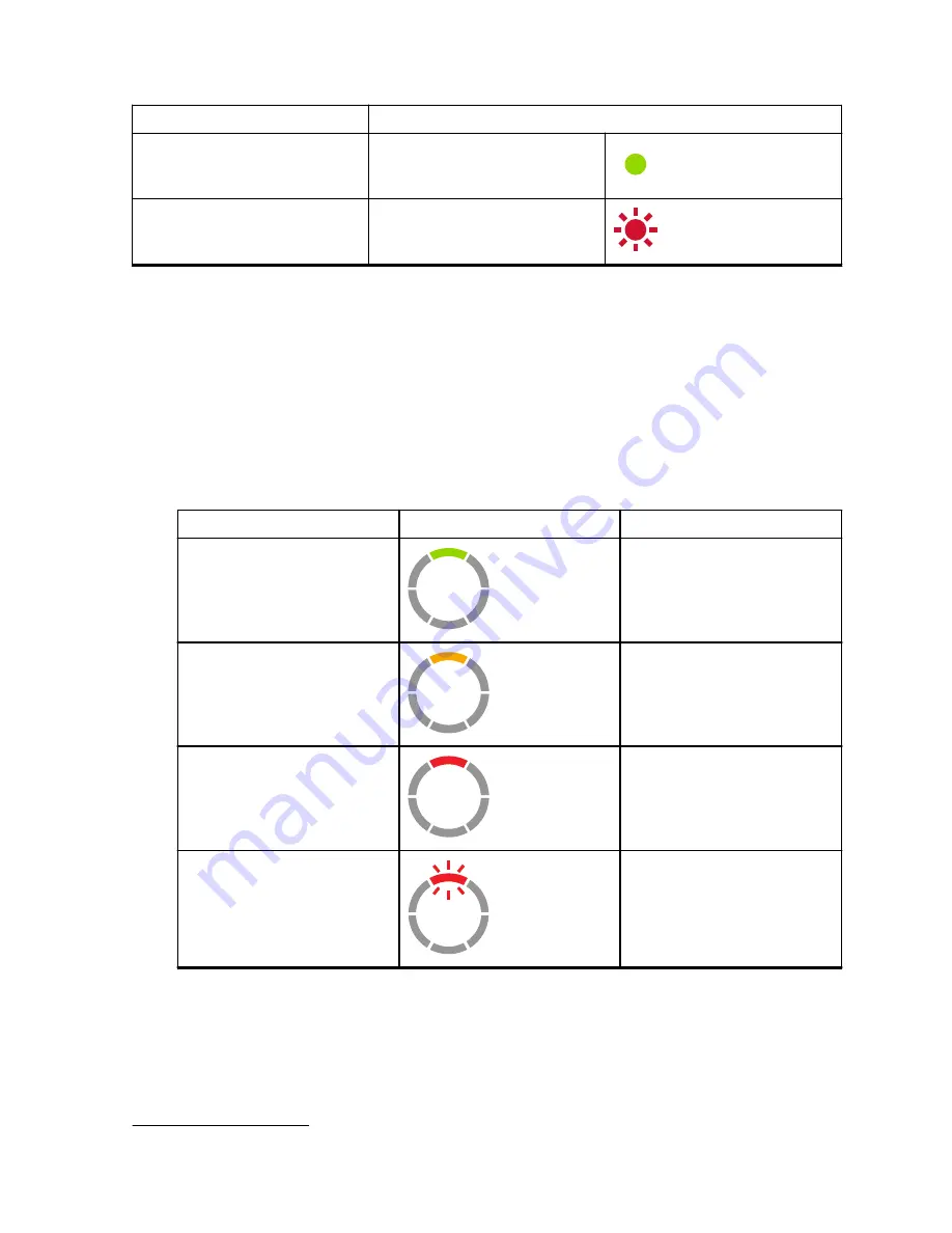
Table 7: Battery Status

Battery Level

LED Indication

Color

High (50 –100%)

Green

Medium (20 – 50%)

Yellow

Low (3 – 20%)

Red

Critical (0 – 3%)

Blinking Red

The radio returns to the current channel color after indicating the battery status.

3

Re-seating the battery pack corrects this issue.

MN007419A01-AA

Chapter 3:  Battery and Charger

  27

Содержание CLP107e

Страница 1: ...CLP107e User Guide MN007419A01 MN007419A01 AA NOVEMBER 2020 2020 Motorola Solutions Inc All rights reserved ...

Страница 2: ...g the Radio On or Off 15 2 4 Adjusting the Volume 15 2 5 Inserting and Removing the Swivel Belt Clip Holster 15 2 6 Transmitting and Receiving 16 2 6 1 Talk Range 17 2 7 Menu Setting 17 2 7 1 Operations Using Menu Settings 17 2 8 Selecting Channels 18 2 8 1 Default Channel Settings for CPS 18 2 8 2 LED Indicators 19 2 8 2 1 Volume LED 19 2 9 Monitoring Channels 20 2 10 Scan 20 2 10 1 Scanning Radi...

Страница 3: ...ns 26 3 9 Checking Battery Status 27 Chapter 4 Radio Programming through CPS 28 4 1 Programming the Radio 28 4 2 Factory Default Settings 29 Chapter 5 Radio Cloning 31 5 1 Cloning Radio Settings 31 5 2 Cloning Radios using the Cloning Cable 31 5 3 Cloning Radios using the Multi Unit Charger 32 5 4 Troubleshooting Cloning Mode 33 Chapter 6 Advanced Radio Configuration 34 6 1 Entering Advanced Radio...

Страница 4: ... place without the express written permission of Motorola Solutions No part of this manual may be reproduced distributed or transmitted in any form or by any means electronic or mechanical for any purpose without the express written permission of Motorola Solutions MN007419A01 AA Documentation Copyrights 4 ...

Страница 5: ...thermore Motorola Solutions reserves the right to make changes to any products herein to improve readability function or design Motorola Solutions does not assume any liability arising out of the applications or use of any product or circuit described herein nor does it cover any license under its patent rights nor the rights of others MN007419A01 AA Disclaimer 5 ...

Страница 6: ...ngly any copyrighted Motorola Solutions computer programs contained in the Motorola Solutions products described in this manual may not be copied reproduced modified reverse engineered or distributed in any manner without the express written permission of Motorola Solutions Furthermore the purchase of Motorola Solutions products shall not be deemed to grant either directly or by implication estopp...

Страница 7: ...damaged in any way Take it to any qualified Motorola Solutions service representatives 6 Do not disassemble the charger it is not repairable and replacement parts are not available Disassembly of the charger may result in risk of electrical shock or fire 7 To reduce risk of electric shock unplug the charger from the AC outlet before attempting any maintenance or cleaning Operational Safety Guideli...

Страница 8: ...To protect your hearing Use the lowest volume necessary to do your job Increase the volume only if you are in noisy surroundings Reduce the volume before connecting headset or earpiece Limit the amount of time you use headsets or earpieces at high volume If you experience hearing discomfort ringing in your ears or speeches that are muffled you should stop listening to your radio through your heads...

Страница 9: ...fy FCC RF energy exposure requirements Before using the radio read the RF Energy Exposure and Product Safety Guide for Portable Two Way Radios which contains important operating instructions for safe usage and RF energy awareness and control for Compliance with applicable standards and Regulations For a list of Motorola Solutions approved antennas batteries and other accessories visit the followin...

Страница 10: ...harmful interference This device must accept any interference received including interference that may cause undesired operation CAUTION Changes or modifications made to this device not expressly approved by Motorola Solutions could void the authority of the user to operate this equipment MN007419A01 AA Notice to Users 10 ...

Страница 11: ...dures that helps promote longer radio life Package Content This section provides information regarding package content for the radio Your product package contains the following products and manuals Quick Start Guide RF Energy Booklet Warranty Card Swivel Belt Clip Holster Lithium Ion Battery and Battery Door Drop In Tray Charger with Transformer1 Audio Accessory2 Audio Jack Cover For product infor...

Страница 12: ...tions of the radio Figure 1 Radio Controls 1 6 5 3 4 2 Item Number Description 1 Power and Battery button 2 Volume Control and Mute button 3 Push to Talk PTT button 4 Smart Status Glow Ring 5 Menu button 6 Accessory Connector MN007419A01 AA Chapter 1 Radio Overview 12 ...

Страница 13: ...Insert the end with the battery contacts before pressing the battery down to secure in place 4 Place the battery door on the radio and push the latch down to lock the battery door Figure 2 Battery Installation 2 2 Connecting Wired Audio Accessory Prerequisites Turn the radio off Procedure 1 Plug the audio accessory into the radio with the unlock icon on the audio accessory facing the front of the ...

Страница 14: ...ton to check for audio through the audio accessory Table 1 Top LED Configuration if Wired Audio Accessory is not Connected or Removed User Mode LED Status Color Turn on radio without an au dio accessory plugged in Solid Blue Audio accessory removed while radio is on Red purple blinks until an audio accessory is plugged in NOTICE Lower the radio volume before placing the audio accessory in or near ...

Страница 15: ...he button 2 5 Inserting and Removing the Swivel Belt Clip Holster The radios offer various flexible carrying accessories For Motorola Solutions approved accessories list refer to Procedure 1 To insert the radio into the holster perform the following steps a Slide the bottom of the radio into the holster b Snap the top of the holster into the radio around the accessory connector 2 To remove radio f...

Страница 16: ...nd Receiving Procedure 1 To transmit calls perform one of the following actions Press and hold the PTT button on the front of the radio Press and hold the PTT button on the wired audio accessory with the inline PTT button 2 Speak clearly into the microphone on the audio accessory 3 Release the PTT button to listen MN007419A01 AA Chapter 2 Getting Started 16 ...

Страница 17: ...t is not necessary to wait for the voice prompt to be completed before continuing with pressing the next button If you are in the menu mode short press PTT or wait 3 seconds to exit the menu Procedure 1 Changing channel a Press Menu button to navigate to Channel b Press the or the button to change channel 2 Entering Monitor Mode a Press Menu button to navigate to Monitor b Press the to activate or...

Страница 18: ...he new channel 3 Press the PTT button to confirm or the channel is activated after three seconds hang time 2 8 1 Default Channel Settings for CPS The table describes the default channel settings for Customer Programming Software CPS Table 3 Channel Settings for CPS CLP107e Models Channel LED Status Color 1 Red 2 Green 3 Yellow 4 Blue 5 Purple MN007419A01 AA Chapter 2 Getting Started 18 ...

Страница 19: ...d the remaining white LED illuminates briefly Advanced radio configuration Blinking green Audio jack feedback LED blinks blue when no accessory at power up LED blinks red and purple fast alternatively when accessory is unplugged 2 8 2 1 Volume LED When volume is increased Smart Status Glow Ring LED lights up in a clockwise direction from the bottom left to the bottom right of the LED ring The foll...

Страница 20: ...g without changing channels 2 10 1 Scanning Radio Channels Procedure 1 To navigate to Scan mode press the Menu button If the scan is off you hear a voice prompt to activate Scan by pressing the or button 2 To activate scan press or button When scan is on you hear a voice prompt to deactivate Scan by pressing the or button 3 To deactivate scan press or button 2 11 Dynamic Talkaround Scan This featu...

Страница 21: ...g Software CPS Long press menu button activates the Escalate Call feature and automatically send Escalate Call Tone on Escalate Call Channel The Escalate Call Hangtime starts after every call ends Radio stays in Escalate Call Hangtime for a predefined period Escalate Call ends when the hangtime expires and radio returns to the previous channel The hangtime is configured through CPS Pressing the PT...

Страница 22: ...igned specifically to be used with a Motorola Solutions charger and vice versa Charging batteries with non Motorola Solutions equipment may lead to battery damage and void the battery warranty Whenever possible maintain the battery temperature to 77 F 25 C room temperature Charging a cold battery below 50 F 10 C may result in leakage of electrolyte and ultimate failure of the battery Charging a ho...

Страница 23: ...Supply Adapter and Drop in Tray Charger The radio is packaged with one Drop in Tray Charger with a transformer NOTICE For information on accessories see Accessories on page 42 Figure 6 Power Supply Adapter and Drop in Tray Charger MN007419A01 AA Chapter 3 Battery and Charger 23 ...

Страница 24: ...rge the battery insert the connector of the power supply into the micro Universal Serial Bus USB port on the front of the drop in tray charger 2 Connect the power supply to a proper AC outlet 3 Insert the battery into the tray with the inside surface of the battery facing the front of the charger See Stand Alone Battery on page 24 4 Ensure that the slots in the battery are correctly engaged in the...

Страница 25: ...rop in Tray Single Unit Charger SUC on a flat surface 2 Insert the connector of the power supply into the Micro USB port on the front of the drop in tray charger 3 Connect the correct power supply to a proper AC outlet 4 Insert the radio with battery installed into the tray facing down and making sure that the charging contacts on the charger are aligned with the contacts on the radio Figure 8 Cha...

Страница 26: ...ed into the charger feature through Customer Programming Software CPS 5 Insert the radio facing down with battery installed into the charging pocket ensuring that the radio contacts are aligned with the MUC contacts NOTICE The battery can be charged by using the slot on the flat surface of the charging pocket Figure 9 Charging Radios 3 8 Charger LED Indications On the drop in charger the radio cha...

Страница 27: ...s Glow Ring and Voice Assisted Operation features show the radio battery status Table 7 Battery Status Battery Level LED Indication Color High 50 100 Green Medium 20 50 Yellow Low 3 20 Red Critical 0 3 Blinking Red The radio returns to the current channel color after indicating the battery status 3 Re seating the battery pack corrects this issue MN007419A01 AA Chapter 3 Battery and Charger 27 ...

Страница 28: ...Programming Software CPS on your computer Ensure that the radio is turned on Procedure 1 Connect the radio by using the Drop in Charger Tray or the Charging Pocket with PROG label on the Multi Unit Charger and CPS Programming Cable4 Figure 10 Programming the Radio through a Single Unit Charger 4 CPS Programming Cable P N HKKN4027_ is an accessory sold separately Contact your Motorola Solutions Poi...

Страница 29: ...d select frequencies and PL DPL codes on each channel 4 To save the settings select Write to radio on the toolbar NOTICE For more information on the CPS see Help menu in the CPS 4 2 Factory Default Settings Your radio is programmed at the factory to the following settings Table 8 CLP107e Channel Number Frequency Settings MHz Code Value Hz Bandwidth kHz 1 464 55 67 0 12 5 2 467 925 3 467 85 4 467 8...

Страница 30: ...Channel Number Frequency Settings MHz Code Value Hz Bandwidth kHz 7 461 1625 8 461 2125 MN007419A01 AA Chapter 4 Radio Programming through CPS 30 ...

Страница 31: ...ssory The MUC does not have to be plugged in for cloning but both radios require charged batteries 5 2 Cloning Radios using the Cloning Cable Prerequisites A fully charged battery on each radio Two Single Unit Charger SUC Kits Both radios are turned off Source radio Radio to be cloned Target radio Radio to which the configuration of the source radio is to be copied Figure 12 Cloning the Radio thro...

Страница 32: ...e the Auto Power Off feature is not applicable 5 3 Cloning Radios using the Multi Unit Charger Prerequisites A fully charged battery on each radio CLP Series Multi Unit Charger MUC Both radios are turned off Source radio Radio to be cloned Target radio Radio to which the configuration of the source radio is to be copied Procedure 1 To put the source radio into clone mode press and hold the source ...

Страница 33: ...on on both Single Unit Chargers SUC 3 Ensure that there is no debris in the charging tray or on the radio contacts and the radio contact is touching the SUC or MUC contact firmly 4 Ensure that the Target Radio is turned on 5 Ensure that the Source Radio is in cloning mode 6 Ensure that the two radios are both from the same frequency band same region and have the same transmission power NOTICE This...

Страница 34: ...de Prerequisites Turn the radio off Procedure 1 Press the PTT button and Power button simultaneously and hold for 3 to 5 seconds until you hear a sound and the voice prompt Programming Mode The LED blinks green 2 To select the settings you want to change press the Menu button The followings are the settings that you can change Channel for multi channel models Frequency Code The voice announcements...

Страница 35: ...frequency and code when transmitting Message Scrambled Scramble Code might be on or the setting does not match other radio settings Change the settings through Customer Pro gramming Software CPS Audio quality not good enough Radio settings might not be match correctly Check the frequencies codes and band widths to ensure the settings are the same in all radios Limited talk range Perform one of the...

Страница 36: ...os are at least 5 ft 1 5 m apart Radios are too far apart or obstacles are in terfering with transmission Low batteries Recharge or replace Li Ion battery NOTICE Extreme operating tem peratures affect battery life See Battery Specifications on page 22 Drop in Charger LED light does not blink Perform one of the following actions Verify that the radio and battery is prop erly inserted Check the batt...

Страница 37: ...If Then Check the charger LEDs indicators to see if the battery has a problem See Charger LED Indications on page 26 MN007419A01 AA Chapter 7 Troubleshooting 37 ...

Страница 38: ...se in water Do not use alcohol or clean ing solutions If the radio is submerged in water Turn the radio off and remove batteries Dry with soft cloth Do not use the radio until it is completely dry NOTICE Radio is IP54 only when the dust cover or audio accessory is plugged into the connector MN007419A01 AA Chapter 8 Use and Care 38 ...

Страница 39: ... 8 88 5 32 203 5 55 116 79 306 103 546 9 91 5 33 210 7 56 125 80 311 104 565 10 94 8 34 218 1 57 131 81 315 105 606 11 97 4 35 225 7 58 132 82 331 106 612 12 100 0 36 233 6 59 134 83 343 107 624 13 103 5 37 241 8 60 143 84 346 108 627 14 107 2 38 250 3 61 152 85 351 109 631 15 110 9 122 69 3 62 155 86 364 110 632 16 114 8 39 23 0 63 156 87 365 111 654 17 118 8 40 25 0 64 162 88 371 112 662 18 123 ...

Страница 40: ... PL 154 Inverted DPL 63 179 Inverted DPL 88 203 Inverted DPL 112 130 Inverted DPL 39 155 Inverted DPL 64 180 Inverted DPL 89 204 Inverted DPL 113 131 Inverted DPL 40 156 Inverted DPL 65 181 Inverted DPL 90 205 Inverted DPL 114 132 Inverted DPL 41 157 Inverted DPL 66 181 Inverted DPL 90 206 Inverted DPL 115 133 Inverted DPL 42 158 Inverted DPL 67 182 Inverted DPL 91 207 Inverted DPL 116 134 Inverte...

Страница 41: ... Customized DPL 142 Inverted DPL 51 167 Inverted DPL 76 191 Inverted DPL 100 216 Customized DPL 143 Inverted DPL 52 168 Inverted DPL 77 192 Inverted DPL 101 217 Customized DPL 144 Inverted DPL 53 169 Inverted DPL 78 193 Inverted DPL 102 218 Customized DPL 145 Inverted DPL 54 170 Inverted DPL 79 194 Inverted DPL 103 219 Customized DPL MN007419A01 AA Chapter 9 Radio Code Chart 41 ...

Страница 42: ...ttery PMLN8066_ CLPe High Capacity Li Ion Battery Door Table 13 Carry Accessories Part No Description PMLN8064_ CLPe Series Magnetic Case PMLN8065_ CLP Series Swivel Belt Clip Holster Table 14 Chargers Part No Description PMPN4020_ CLP Series Multi Unit Charger MUC Kit PMPN4018_6 CLP Series Single Unit Charger SUC Kit Table 15 Programming Cables Part No Description HKKN4027_ CLP Series CPS Cable H...

Отзывы: