PTP SOLUTIONS GUIDE
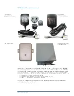
Regardless of the application, the Motorola PTP 300, 400, 500 and 600 systems create a wireless Ethernet
link between two points. Each point consists of an indoor unit and an outdoor unit. The two endpoints
communicate via radio waves over channels varying in bandwidth between 10 and 12 MHz (PTP 400 Series),
15 MHz (PTP 300 and PTP 500 Series) and 5 and 30 MHz (PTP 600 Series). The channel raster is designed
to ensure maximum flexibility in deciding channel occupancy. This greatly increases the probability that
customers can find at least one usable channel in an already crowded hub-site.
Each outdoor unit utilizes two transceivers coupled to a baseband converter. The two pairs of transceivers
connect with one another, enabling four different transmitter/receiver combinations – and so four distinct
transmission beams. This greatly reduces the effects of fading and increases the probability that data will
get through.
PTP 300, 400, 500 and 600 Series bridges use a unique combination of innovative technologies to deliver
exceptional range, capacity, reliability and throughput – especially in nLoS or NLoS conditions, and in areas
where there is significant RF interference, such as a city. The nLoS and NLoS capabilities provide a high
tolerance for obstructions and enable network operators to establish network connections over hills, around
buildings, through trees and over water.
pTp 300, 400, 500 and 600 Series Similarities:
PTP 300, 400, 500 and 600 Series bridges share many feature characteristics, including:
•
Advanced Spectrum Management with
Intelligent
Dynamic Frequency Selection (
i
-DFS)
automatically changes channels to avoid interference and combat link fading without user
intervention. At power-up and throughout operation, the radio samples the band up to 1,200 times a
second (PTP 600 Series) or up to 400 times a second (PTP 300, 400 and 500 Series) and automatically
switches to the clearest channel. The 30-day, time-stamped database alerts the network operator to
any interference that does exist and provides statistics to help analyze these patterns. This Advanced
Spectrum Management capability creates virtually interference-free performance in the band.
•
Adaptive Modulation
ensures maximum throughput optimized for the radio path, even as path
characteristics change. The transmitter and receiver negotiate the highest mutually sustainable data
rate – then dynamically “upshift” and “downshift” the rate as RF conditions change.
•
Dual polarized Antennas
– two transmitters and two receivers are used to establish a link, enabling
four different transmitter/receiver combinations. By creating four distinct transmission beams, the
chances that data will get through increase significantly.
•
Multiple-Input Multiple-Output (MIMO)
transmits multiple signals which are de-correlated
temporarily and spatially. Being de-correlated, each path fades at different times, and the receiver is
able to select the best signal at any time, resulting in better performance and link availability. The radio
radiates multiple beams from the antenna – the effect of which significantly protects against fading
and increases the probability of making a connection and reading the transmitted data. Plus, the radio
will intelligently switch to “Dual Payload” mode if RF conditions will support it. In this mode, different
data can be transmitted in parallel on each transmitter, effectively doubling the bandwidth at the
higher modulation rates.
•
Intelligent
Orthogonal Frequency Division Multiplexing (
i
-OFDM)
– in addition to MIMO
transmitting the data twice,
i
-OFDM sends transmissions over multiple frequencies, or sub-carriers.
The multiple sub-carriers result in higher spectral efficiency and higher resistance to:
(1) Multi-path interference which occurs when objects in the air gap split a beam into parts that travel
different paths and interfere with each other at the receiver.
(2) Frequency selective fading which occurs when amplitudes of arriving signals cancel each other out
at the receiver.
In typical radios this would be a problem, but with PTP 300, 400, 500 and 600 Series radios,
i
-OFDM
actually helps the radios re-correlate the interfering signals, improving the chance of receiving the
signal through reflective behavior.
Key pTp 300, 400, 500 and 600 Technical Features

