background image

2

2A

2B
3A

4A
4B
5A
5B

6A
6B

13B

10B

9A

15A

12A

7A

14A

11A

9B

15B

12B

8

14B

11B

10A

16A
16B

13A

17

19

20

18A
18B

1

EN

01. SAFETY INSTRUCTIONS

02. THE CONTROL BOARD

03. INSTALLATION

04. PROGRAMMING (P)

05. PROGRAMMING (E)

06. DISPLAY

08. TROUBLESHOOTING

09. CONNECTION SCHEME

STANDARDS TO FOLLOW

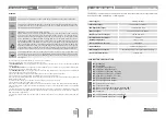
TECHNICAL SPECIFICATIONS

PROGRAMMING PRE-RECOMENDATIONS

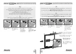
ESSENTIAL STEPS FOR INSTALLATION

TRANSMITTERS

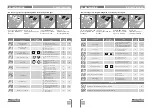
"P" MENU FUNCTIONS
"E" MENU FUNCTIONS

P0-AUTOMATIC PROGRAMMING OF THE COURSE

E2-COURTESY LIGHT TIME

P6-SAFETY BAND

P3-PEDESTRIAN COURSE TIME

E6-DECELERATION SPEED

P9-DISTANCE PROGRAMMING

P1-SETTING THE DECELERATION TIME

E3-FOLLOW ME

P7-OPERATING LOGIC

P4-PAUSE TIME

E7-MANEUVERS COUNTER

E0-PRESENT MAN

P2-SETTING STRENGTH AND SENSITIVITY

E5-ELECTRIC BRAKE

P8-FLASHING LIGHT

P5-PHOTOCELLS PROGRAMMING

E8-RESET - RESTORE FACTORY VALUES
E9-RGB FLASHING LIGHT

E1-SOFT START

DISPLAY INDICATIONS

INSTRUCTIONS FOR FINAL CONSUMERS/ TECHNICIANS

CONNECTIONS MAP

CAPACITOR SCHEME
INPUTS TEST

07. COMPONENTS TEST

00. CONTENT

INDEX

P0-SEMI-AUTOMATIC PROGRAMMING OF THE COURSE

Содержание MC50SC

Страница 1: ...24V 1 2 v7 2 REV 03 2021 EN USER INSTALLER MANUAL MC50SC...

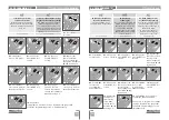
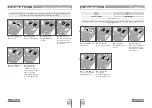
Страница 2: ...P0 AUTOMATIC PROGRAMMING OF THE COURSE E2 COURTESY LIGHT TIME P6 SAFETY BAND P3 PEDESTRIAN COURSE TIME E6 DECELERATION SPEED P9 DISTANCE PROGRAMMING P1 SETTING THE DECELERATION TIME E3 FOLLOW ME P7 OP...
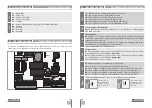
Страница 3: ...not make any changes to the automation components and or their accessories Control board for indoor use with 230V connection Keep remote controls away from children to prevent the automated system fro...

Страница 4: ...vated It is mandatory the use of limit switches Safety circuits 01 This input allows connection of safety bands The device operates according to programming set in the P6 menu page 10B 02 This input a...

Страница 5: ...s not match the gate s movement turn off the control board from the power supply e swap the 5 and 7 wires from CN1 and check if it is correct with 3 and 4 from CN2 ESSENTIAL STEPS FOR INSTALLATION 03...

Страница 6: ...cells in opening 00 00 10A Safety band Security Band Disabled Security Band Activated 8k2 input NC input Band in closure Band in opening 00 01 00 10B OperatiNG logic Automatic mode function Step by st...

Страница 7: ...seconds 02 P0 appears Press MENU for 1 second 04 When MA appears press MENU for 1 second The motor will start a slow closing of the door 05 When it reach the closing limit switch it will open automati...

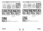
Страница 8: ...vement inertia which could cause it to get stuck factory default 3 min max 0s 03 P1 appears Press MENU for 1 second 04 tP appears Press MENU for 1 second 06 Press MENU for 1 second to save the set val...

Страница 9: ...P If you set the sensitivity FS to a value greater than 1 the force FO is automatically set to 9 without the possibility to change it Note If the control board has very high sensitivity values you ma...

Страница 10: ...defined time Pause time adjustment of the total closure Allows you to set the time that the gate will remain open Pause time adjustment of the pedestrian closure Allows you to set the time that the ga...

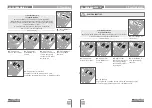
Страница 11: ...ault 00 02 P0 appears Press five times 02 P0 appears Press six times 03 P5 appears Press MENU for 1 second 03 P6 appears Press MENU for 1 second 04 HE appears Press MENU for 1 second 01 Press MENU for...

Страница 12: ...or control board start button factory default 00 02 P0 appears Press seven times 01 Press MENU for 3 seconds 03 P7 appears Press MENU for 1 second 05 Press MENU to save the defined function 04 Appear...

Страница 13: ...viously stored transmitter memorize transmitters page 5B Factory default 00 Distance programming operation PGM ON Press the keys indicated in the picture at the same time for 10 seconds and the flashi...

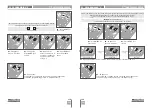
Страница 14: ...ned function SOFT START 01 Press MENU for 10 seconds 02 E0 appears Press twice 03 E2 appears Press MENU for 1 second 05 Press MENU to save the defined time This menu allows you to define the time from...

Страница 15: ...es 03 E3 appears Press MENU for 1 second 05 Press MENU to save the defined function 06 E4 appears is inactive To advance to the E5 menu press once To exit the programming press simultaneously 00 disab...

Страница 16: ...maneuver it is understood by opening and closing The control board reset does not erase the maneuvers count Example 13456 maneuvers 01 Hundreds of thousands 34 Thousands 56 Dozens display flashes disp...

Страница 17: ...ds RGB OUTPUT 05 Press MENU for 1 second to save the defined function 06 E1 appears To exit the programming press simultaneously 01 Press MENU for 10 seconds 02 E0 appears Press eight times 02 E0 appe...

Страница 18: ...t switch enabled No limit switches or both open limit switches In pause time Security Band under pressure In pedestrian pause time Pedestrian button being pressed Memory full Start button being presse...

Страница 19: ...ion correctly The order of capacitor wires linked with the automatism wires are not important as long as you link one to the Brown wire and the other to the Black one The common wire of the motor must...

Страница 20: ...works the problem is from control board Pull it out and send it to our MOTORLINE technical services for diagnosis 4 If the motor doesn t work remove them from installation site and send to our MOTORL...

Страница 21: ...1 2 3 4 5 6 7 8 9 V R G B RG DV 12 24V DV 12 24V COM NC CN1 CN2 CN3 CN4 CN5 20 EN Antenna Limit switch CLOSE OPEN key selector pushbutton Pedestrian key selector pushbutton Total Safety Band or or Pho...

Отзывы: