AUTOGUIDÉE SCD
13
MONTAGE GÉNÉRAL
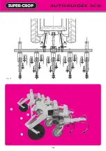
Une bineuse SUPER-CROP SCD se compose normalement :
• d'une barre porte-outils (A)
• de 3 pièces d'attelage, c'est-à-dire d'une pièce centrale (B) et de 2 brides
latérales (C)
• d'un certain nombre de corps d'éléments bineurs (D) : 5 pour bineuse
4 rangs - 7 pour 6 rangs...
• de 2 stabilisateurs (E) (coutres à disques)
• d'une béquille (F)
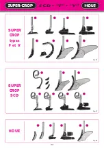
• de l'équipement : dents flexibles avec socs et traverses, disques protège
plants...
OPÉRER DE LA MANIÈRE SUIVANTE POUR LE MONTAGE
1. Repérer exactement sur la barre les emplacements d'éléments (D) en
fonction des inter-rangs.
2. Fixer le 3
e
point (B) puis de part et d'autre et à EGALE DISTANCE de ce
3
e
point les 2 brides latérales (C) à un écartement tel, qu'après attelage
au tracteur, les rotules des bras de relevage soient distantes de 85 à 88 cm.
L'axe d'attelage des brides (C) est déporté ce qui permet de toujours
trouver un emplacement libre sur la poutre.
Attention : Ces 2 brides (C) se plaquent sous la barre (fig. 2) et non sur
l'avant de la barre.
3. Atteler à un tracteur la barre porte-outils ainsi munie de son attelage.
4. Fixer, aux emplacements précédemment repérés, les corps d'éléments
(D).
5. Fixer les 2 ensembles coutres stabilisateurs (E) sur l'avant des éléments
extérieurs.
6. Placer la béquille (F) à un endroit libre et accessible vers le centre de la
machine.
7. Monter les équipements (traverses-dents-disques...) en respectant les
conseils de la page suivante.
SE REPORTER AUX PAGES 16-17 POUR LA MISE EN ROUTE
GENERAL ASSEMBLY
The SCD “SUPER-CROP” interrow cultivator is normally composed of :
• a toolbar (A)
• 3 point hitch, consisting of a central mast (B) and 2 lower mounting
brackets (C)
• a certain number of cultivator units (D) : 5 for the 4 row cultivator - 7 for
the 6 row model, etc.
• 2 stabilizers (E) (disc coulters)
• a toolbar stand (F)
• the accessories : spring tines with foot pieces and cross-bars, rotating
cultivator shields...
PROCEED AS FOLLOWS FOR ASSEMBLY
1. Mark the toolbar the exact locations for placement of the cultivating
units (D) according to the row spacing to be cultivated.
2. Fasten the central mast (B) then on either side and at an EQUAL
DISTANCE from this central mast, the 2 lower mounting brackets (C),
with such spacing that after hitching to the tractor, the balls of the lift
arms are 85 to 88 cm (34-35") apart. The hitch pin of the lower
mounting brackets (C) is offset which always allows for proper
placement on the bracket.
Attention : These 2 brackets (C) are positioned underneath the toolbar
and not in front of the toolbar.
3. Hitch the toolbar to the tractor at the 3 point hitch.
4. Attach units (D) to the locations previously marked.
5. Mount the 2 stabilizing coulter units (E) in front of the outside units.
6. Place the toolbar stand (F) in a clear and accessible location near the
center of the machine.
7. Mount the accessories (cross-bars, tines, discs ... ) following the
instructions of the next page.
FOR OPERATING INSTRUCTIONS, PLEASE REFER TO PAGES 16-17
MONTAGEANLEITUNG
Die Hackmaschine SUPER-CROP SCD besteht aus :
• einem Werkzeugrahmen (A)
• drei Kupplungsteilen - 1 Oberlenkeranbaubock (B) und 2 Unterlenkeran-
baulaschen (C)
• Hackelemente (D) : 5 Stück bei 4-reihiger und 7 Stück bei 6-reihiger
Hackmaschine
• zwei Scheibenseche (E) für Selbstlenkung
• einer Abstellstütze (F)
• Federzinken mit Scharen und Querstreben und Pflanzenschutzscheiben
DIE MONTAGE FÜHREN SIE WIEFOLGT DURCH :
1. Markieren Sie auf dem Rahmen die Punkte, wo die Elemente (D)
angebaut werden müssen - je nach Reihenweite.
2. Den Oberlenkeranbaubock (B) befestigen Sie genau in der Mitte der
Anbauschiene. Die zwei Unterlen-keranbaulaschen (C) werden im
gleichen Abstand vom Oberlenkeranbaubock montiert. Achten Sie
darauf, daß die Unterlenkeranbaulaschen nach außen stehen und ein
Spreizmaß von 85-88 cm haben.
3. Bauen Sie jetzt den Werkzeugrahmen an Ihren Schlepper an.
4. Die Hackelemente werden an den vorher markierten Punkten auf dem
Rahmen befestigt.
5. Die beiden Scheibenseche (E) montieren Sie an die beiden äußeren
Enden des Rahmens, so daß diese nach vorne stehen.
6. Die Abstellstütze (F) an eine freie Stelle im mittleren Bereich der
Maschine montieren.
7. Die Ausrüstungen (Querträger - Federzinken - Schutzscheiben) je nach
Anweisung der nächsten Seiten anbringen.
BEACHTEN SIE DIE SEITEN 16-17 FÜR DIE INBETRIEBNAHME !
MONTAGGIO GENERALE
Una sarchiatrice SUPER-CROP SCD consta normalmente di :
• Una barra porta attrezzi (A)
• 3 pezzi di attacco, cioè un pezzo centrale (B) e 2 flange laterali (C)
• Certo numero di corpi di elementi sarchiatori (D) : 5 per sarchiatrice 4 file -
7 per 6 file…
• Stabilizzatori (E) (coltri a dischi)
• Un sostegno (F)
• L'attrezzatura : denti flessibili con vomeri e traverse, dischi proteggi-
piante…
PROCEDERE NEL MODO SEGUENTE PERE IL MONTAGGIO
1. Identificare essatamente sulla barrale posizioni degli elementi (D) in
funzione dell'interfila.
2. Fissare il terzo punto (B) e dopodiché da una parte e dall'altra e a
UGUALE DISTANZA di questo terzo punto le 2 flange laterali (C) a un
intervallo tale che dopo l'accoppiamento al trattore, i giunti a sfera dei
bracci di sollevamento siano distanti di 85 a 88cm. L'asse di attacco
delle flange (C) é diportato ciò che permette di trovare sempre un posto
libero sulla trave.
Attenzione : queste 2 flange si fissano sotto la barra (fig. 2) ma non sulla
parte anteriore della barra.
3. Accoppiare a un trattore la barra porta-attrezzi così provista del suo
attacco.
4. Fissare i corpi di elementi (D) alle posizioni previamente identificati.
5. Fissare le 2 insiemi coltri stabilizzatori (E) sulla parte anteriore degli
elementi esterni.
6. Fissare il sostegno (F) a un luogo libero ed accessibile verso il centro
della macchina.
7. Montare gli attrezzi (traverse-denti-dischi…) osservando le
racommandazioni della pagina seguente.
VEDERE LE PAGINE 16-17 PER L'AVVIAMENTO
Содержание SUPER-CROP C1L
Страница 14: ...12 AUTOGUID E SCD Fig 1 Fig 2 Fig 4 Fig 3 Fig 5 F D C C B E...
Страница 16: ...AUTOGUID E SCD 14 Fig 8 Fig 6 Fig 10 Fig 9 Fig 12 Fig 11 8 1 3 6 7 7 9 2 4 5...
Страница 18: ...AUTOGUID E SCD 16 Fig 13 Fig 14 3 2 1 3...
Страница 24: ...22 Fig 23 Fig 25 Fig 24 2 1 3 4 Bineuse houe 5 l ments avec direction Bineuse houe 3 l ments sans direction...
Страница 32: ...30 SCD F V CHASSIS A REPLIAGE MANUEL Fig 39 Fig 42 Fig 44 Fig 43 Fig 45 Fig 46 Fig 40 Fig 41 1 5 4 1 3 3 2...
Страница 36: ...34 SCD FERTILISEUR RECTANGULAIRE sur bineuse ch ssis rigide Fig 58 Fig 59 Fig 60 Fig 61 Fig 62 3 1 2 1 3...
Страница 40: ...38 SCD FERTILISEUR GRANDE CAPACIT sur bineuse SCD Fig 76 Fig 77 Fig 78 5 6 6 7 9 9 7 4 1 1 4 2 5 3 8...
Страница 46: ...44 SCD BINEUSE AUTODIRIG E SCH MA LECTRIQUE Fig 94 Fig 97 Fig 96 Fig 95 Fig 98 2 1...


