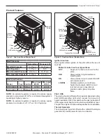
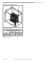


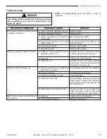


Unvented Cast Iron Gas Stoves
13
3-90-58D6002
Monessen • Concorde VF Installation Manual_R11 • 02/17
Electrical Wiring (Millivolt)
The millivolt valve is a self-powered combination gas control
THAT DOES NOT REQUIRE 110V AC TO OPERATE.
Connect Optional Wall Switch
1. Use 18 awg, two-wire cable, 15 feet maximum length.
2. At one end of the cable, connect both wires to the wall
switch. At the other end, connect one wire to TP/TH and
one wire to TH, or connect the wall switch to the two male
(0.25") terminals on the left side of the unit. The color of
the wires does not matter.
Check System Operation
The millivolt system and individual components may be
checked with a millivolt meter having a 0-1000 mV range.
Conduct each check shown in chart below by connection
meter test leads to terminals as indicated.
A. Complete MilliVolt System Check
(“A” Reading - Thermostat contacts CLOSED -
Control Knob “ON” - Main burner should turn ON)
a. If the reading is more than 100 millivolts and the
automatic valve still does not come on, replace the
control.
b. If the closed circuit reading (“A” reading) is less
than 100 millivolts, determine cause for low reading,
proceed to Section B below.
B. Thermopile Output Reading Check
(“B” Reading - Thermostat contacts OPEN - Main
burner OFF)
1. Check gas pressure to the unit. If gas pressure is within
minimum and maximum on data plate, then check pilot
voltage, 325 millivolts minimum. If the minimum millivolt
reading is not obtainable, replace pilot.
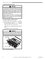
Label all wires prior to disconnection when servicing
controls. Wiring errors can cause improper and
dangerous operation. Verify proper operation after
servicing.
CAUTION
!
Check
Test
To Test
Connect
Meter Leads
to Terminals
Switch or
Thermostat
Contacts
Meter
Reading
Should Be
A
Complete
System
2 & 3
Closed
Closed
B
Thermopile
1 & 2
Open
Open
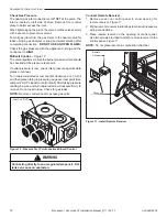
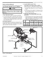
Figure 12 - Wiring Diagram
ST1176
Millivolt valve wiring
On/Off Switch
Wall Switch
Optional Wall
Switch or Remote
ODS Pilot
Millivolt Valve
Connection
1 = TP
2 = TP, TH
3 = TH
Switch
Spade Terminal
On/Off Switch
ODS Pilot
3 1 2