


14
English
5.3.7 Telephone bell or night bell
A telephone bell or night bell may sound via the
PA system (e . g . during a round at night), if required .
1) Feed the control voltage for the bell (e . g . 8 V/
50 Hz) to the connections NIGHT RINGER (26) .
2) Press the button TEL (13) .
3) Actuate the bell and adjust the volume of the
ringing tone created by the amplifier with the
control RINGER (11) .
4) Switch the bell function on or off with the but-
ton TEL according to requirements .
Note:
The bell has lowest priority .
5.3.8 Telephone switchboard
Announcements via the PA system can be repro-
duced from a telephone switchboard .
1) Feed the telephone signal (line level) to the
terminals PAGING IN (27) .
2) Adjust the volume during an announcement
with the control PAGING (12) .
Note:
Telephone announcements have 3
rd
priority .
5.3.9 Switch for announcements in all zones
For remote control of the following functions con-
nect a switch to the terminals MESSAGE FIRST
PRIORITY (28):
1 . All PA zones are switched on and set to maxi-
mum volume [as with the button ALL CALL (4)] .
2 . When using the digital message insertion PA-
1120DMT, the announcement of the memory
M 6 is automatically called . For this purpose,
connect the jumper MS 2 prior to installing the
insertion to the position “PRI TO PACK” (see
layout plan on page 48) . Thus, the announce-
ment of the memory M 6 takes first priority .
Instead of the switch, it is also possible to
connect an alarm detecting contact, e . g . for an
automatic fire alarm announcement .
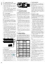
3 . If the amplifier is at the same time to be switched
on by the switch or alarm detecting contact, con-
nect a diode of type 1N4007 according to fig . 7
between the upper terminal MESSAGE FIRST
PRIORITY and the left terminal POWER REM .
Z5
Z4
Z3
Z2
Z 1
4
Ω
100V
Z6
LOW
IMP
NIGHT
RINGER
PAGING
IN
MESSAGE
FIRST
PRIORITY
HIGH
IMP
SPEAKER ZONES
ATT. OUTPUTS
TEL
1N4007
24 V
⎓
/20 A
POWER REM.
➆
Automatic switch-on of the amplifier and
activation of the announcement M 6
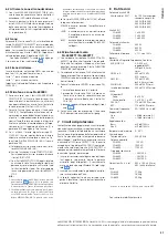
5.3.10 Emergency priority relays
If PA volume adjusting controls with emergency
priority relays (e . g . series ATT-3 . .PEU or ATT-5 . .PEU
from MONACOR) are inserted between the ampli-
fier and the speakers, important announcements
can also be heard at the volume “zero” .
1) For this purpose connect a desk microphone
PA-4000PTT or PA-4300PTT (chap . 5 .3 .3) .
2) Connect the emergency priority relay according
to fig . 8 to the terminals PRIORITY RELAY OUT-
PUT (47) . The output allows a load of 200 mA .
3) Set the switch PRIORITY at the microphone to
position ON (downwards) .
4) When actuating the TALK button now, the
speakers are set to maximum volume by the
relays .
100V
ATT-…
PA-6240/-6480/-6600
Speaker
24 V
Switch Line
100 V
Audio Line
10
0
PA-4000PTT PA-4300PTT
PRIORITY RELAY
OUTPUT
24 V, max. 0,2 A
➇
Emergency priority relays
5.3.11 Switch for switching on and off
by remote control
The amplifier can be switched on and off by remote
control with a switch connected to the contacts
POWER REM (36) . For this purpose, the amplifier
must not be switched on with the POWER switch (19)
or not be connected to the emergency power supply .
5.3.12 Power supply and
emergency power supply
1) Finally connect the supplied mains cable to
the mains jack (35) first and then to a socket
(230 V/ 50 Hz) .
2) For continuous operation of the amplifier in case
of a possible mains failure, connect a 24 V emer-
gency power supply unit (e . g . PA-24ESP from
MONACOR) to the terminals 24 V
⎓
(37) . With a
cable length of up to 6 m, a cable cross section
of 4 mm
2
is required as a minimum .
Note:
1 . If the 24 V voltage from the emergency power supply
unit is present at the terminals 24 V
⎓
, the amplifier
cannot be switched off with the switch POWER (19) . In
case of a mains failure or if it is switched off, it switches
automatically to the emergency power supply .
2 . Even if the amplifier is switched off, it consumes some
power . Therefore, disconnect the mains plug from the
socket and, if necessary, disconnect the emergency
power supply unit if the amplifier will not be in oper-
ation for a longer time .
5.4 Defining the priority
of the input signals
A priority is assigned to all input signals . A signal of
a higher priority always covers a signal of a lower
priority when both signals are present at the ampli-
fier at the same time . Signals of the same priority
are mixed . The following table gives an overview
and shows possibilities of modification .
Priority Signal
Condition
Modification
1
Announcement M 6
from digital
message insertion
PA-1120DM
jumper MS 2 on
PRI TO PACK
switch at (28)
closed
2
desk microphone
PA-4000PTT
PA-4300PTT
DIP switch
PRIORITY on
microphone
to ON
switch to
OFF =
4
th
priority
2
zone paging
microphone
PA-6000RC
switch on
connection
module to
PRIORITY
switch to
SLAVE =
4
th
priority
2
chime
—
—
3
telephone switch-
board at terminal (27)
—
—
4
inputs 1, 2 and 3
DIP switch (34)
to OFF
1
DIP switch
to ON =
3
rd
piority
siren
—
—
5
extension
insertions
jumper MS 2
to SLAVE
1
jumper MS 2
to PRI TO PACK
= 2
nd
piority
inputs 4 and 5
—
—
telephone bell or
night bell
—
—
1
Factory setting
2
The desk microphone PA-4000PTT
/
PA-4300PTT
uses the input 1 and the zone paging microphone
PA-6000RC the input 2 . Via the corresponding
DIP switch MIC PRIORITY (34), the microphones can
also be set to 3
rd
priority .
6 Operation
If the amplifier is switched off and if no 24 V voltage
from an emergency power supply unit is present
at the terminals 24 V
⎓
(37), the LED STAND-BY
(20) lights up .
1) Prior to the first switching-on, set the five level
controls (7) for the inputs 1 to 5 and the control
MASTER (17) to position zero for the time being .
2) Switch on the amplifier with the POWER switch
(19) or with a switch connected to the terminals
POWER REM (36) . The green LED STAND-BY
extinguishes and the yellow LED POWER (21)
lights up .
6.1 Adjusting the volume
1) First adjust the volume desired as a maximum
for announcements of highest priority . For this
purpose, press the button ALL CALL (4) for the
time being . According to the equipment avail-
able, make an announcement:
a) With a digital message insertion, call the
announcement from the memory M 6 via
a switch at the terminals MESSAGE FIRST
PRIORITY (28) . Set the control LEVEL at the
insertion approximately to the position 7 .
b) With a desk microphone connected to the
jack PA-4300PTT (45) or PA-4000PTT (46),
set the level control (7) of the input 1 ap-
proximately to the position 7, and make an
announcement .
c) In case of a zone paging microphone PA-
6000RC, set the level control (7) of input 2
approximately to position 7, press the button
ALL CALL (58), and make an announcement .
d) When using another microphone, set the
level control (7) of the corresponding input
approximately to position 7, and make an
announcement .
2) During an announcement, adjust the volume
with the control MASTER (17) . In case of over-
load, the red LED CLIP lights up in the level
indication (5) . Then reduce the volume with the
control MASTER .
3) To adjust the volume for normal announce-
ments, disengage the button ALL CALL again .
For this purpose, press all buttons (3) of the
individual PA zones .
4) Make an announcement as described under
item 1) b or d .
Notes:
1 . On the PA-4000PTT / PA-4300PTT, set the switch
PRIORITY to the upper position .
2 . Do not make the announcement via a PA-6000RC
because its volume is independent of the zone
volume switches (2) .
5) Do not change the control MASTER (17) but
adjust the desired volume separately for each
zone with the corresponding zone volume
switches (2) during the announcement .
6) Then adjust the volume for the signals of the
other inputs (e . g . background music) with the
control LEVEL (7) of the corresponding input .
7) For each input used adjust the sound with the
corresponding controls “Bass” and “Treble” (6) .
Adjust the sound for an insertion in the com-
partment (1) with the controls PACK (8) .
8) It may be necessary to readjust once again the
volume of the input signals with the correspond-
ing level controls (7) .
9) Turn the level controls (7) of the inputs not used
to zero .
Note:
For the inputs 1 to 3, the input sensitivity can be
adjusted with the controls GAIN (43) . If a level control (7)
must be turned up very far or almost be closed to obtain
the desired volume ratio to the other inputs, modify the
input sensitivity with the corresponding control GAIN .


