Tool Kit for P-Lock Flag Female Terminal
Doc No: ATS-6382566HM Release Date: 01-27-13
UNCONTROLLED COPY
Page 2 of 8
Revision: A
Revision Date: 01-27-13
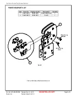
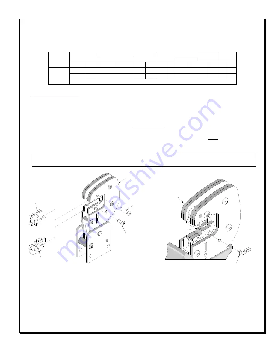
ANVILS
POWER
CRIMP
HEAD
Figure 1
PUNCHES
M4 X 8 LONG
BHCS
M4 X 18 LONG
BHCS
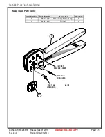
HAND TOOL
OPEN
TERMINAL
Figure 2
NEST
CONDITIONS:
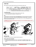
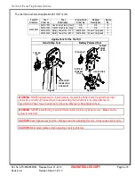
After crimping, the conductor profiles should measure the following (See notes below).
Terminal
Series No.
Wire Size
Conductor Crimp
Insulation Crimp
Pull Force
Minimum
●
Punch
Set
Height
Width (Ref) Height Width (Ref)
AWG mm
2
mm
In.
mm
In. mm In. mm
In.
N Lbs
A
B
104441
24
N/A 0.85-0.95 .033-.037 1.60 .063 --- ---
---
--- 49.0 11.0 X
24 + 24 N/A 0.95-1.05 .037-.041 1.60 .063 --- ---
---
--- 49.0 11.0
X
●
See Page 3, Figure 3 to determine which Punch Set to use for each wire awg.
Tool Qualification Notes:
1. Pull Force should be measured with no influence from the insulation crimp.
2. The above specifications are guidelines to an optimum crimp.
Note:
A crimp height chart is provided with this manual as Reference Only. Due to the wide range of wires, strands,
insulation diameters, and durometers, actual crimp height measurements may very slightly. An occasional,
destructive, pull force test should be preformed to check hand tool crimp. Pull Force value must exceed the
minimum pull force specifications listed.
CAUTION:
Install only Molex terminals listed above with this tool. Do not crimp hardened objects as damage
can occur to the tool or die.
INSTALLATION
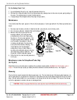
To install the Tool Kit into the Power Crimp Head follow the steps below:
Anvils and Punches Installation
1.
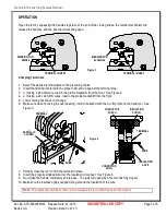
Insert the Anvils into the bottom slots of the nest. Install the M4 x 8 long BHCS and tighten in place.
2.
Insert the Punches into the top slots of the nest. Install the M4 x 18 long BHCS and tighten in place. See
Figure 1.


