background image

SpectraMax M2 and M2e Microplate Reader User Guide

15

0112-0102 E

Control Panel

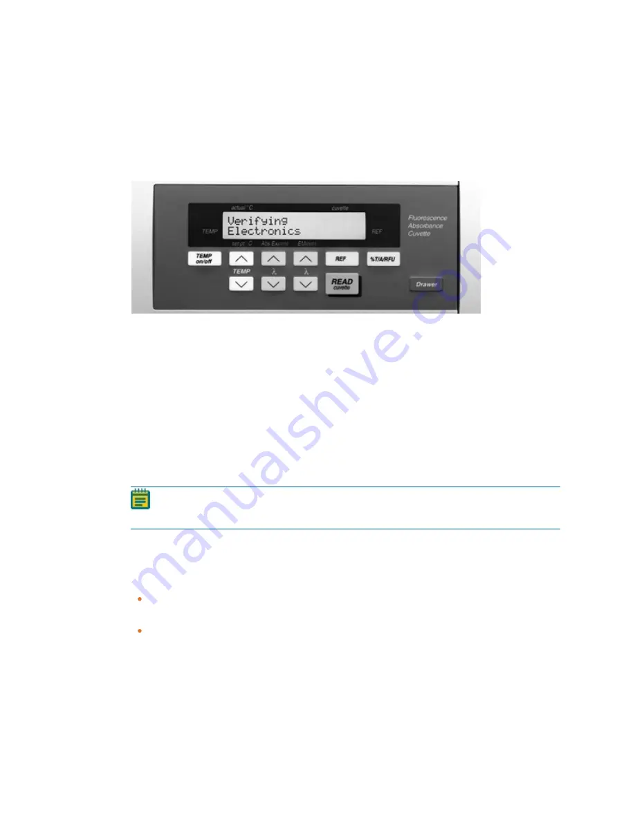
The instrument control panel works in conjunction with the SoftMax Pro Software to open
the plate drawer, adjust the temperature, and to set the wavelengths for cuvette reads. See
the

SoftMax Pro Data Acquisition and Analysis Software User Guide

.

To change the contrast of the display, press

%T/A/RFU

, and then press

Temp

p

or

q

.

The left side of the control panel displays the actual temperature inside the cuvette chamber
above the display of the temperature you set for the cuvette chamber. If the temperature
inside the cuvette chamber is not at the set temperature, the indicator blinks. The
temperature inside the plate chamber lags slightly behind the temperature inside the
cuvette chamber. The temperature inside the plate chamber displays in the software.

The center of the control panel displays the absorbance/excitation and emission
wavelengths the instrument uses for a cuvette read.

The right side of the control panel displays the data the instrument receives from a cuvette
reference read as percent transmission, absorbance, or relative fluorescence units. If you do
not do a reference read, the indicator blinks.

Note:

Settings you enter in the software override the corresponding control panel

setting.

Temp On/Off

The

Temp On/Off

button enables or disables the incubator that controls the temperature

inside the cuvette chamber and the plate chamber.

When the incubator is on, the control panel displays the temperature inside the cuvette
chamber above the display of the temperature you set.
For the Kinetic and Spectrum read types, the temperature buttons on the control panel
are disabled.

Содержание SpectraMax M2

Страница 1: ...0112 0102 E October 2018 SpectraMax M2 SpectraMax M2e Multi Mode Microplate Readers User Guide...

Страница 2: ...and or license to use or permit others to use such manufacturers and or their product names as trademarks Each product is shipped with documentation stating specifications and other technical informa...

Страница 3: ...tting Started 14 Control Panel 15 Cuvette Chamber 17 Plate Drawer 18 Plate Adapter 19 Chapter 4 Operating the Instrument 20 Temperature Settings 20 Wavelength Settings 21 Read a Plate 22 Read a Cuvett...

Страница 4: ...User Guide 4 0112 0102 E Chapter 7 Troubleshooting 39 Opening the Drawer Manually 43 Obtaining Support 44 Appendix A Specifications 45 System Diagrams and Dimensions 51 Appendix B Accessories 53 Appe...

Страница 5: ...ied by Molecular Devices the protection provided by the equipment might be impaired Warnings Cautions Notes and Tips All warning symbols are framed within a yellow triangle An exclamation mark is used...

Страница 6: ...rective contact your dealer or local Molecular Devices office for the procedures to facilitate the proper collection treatment recovery recycling and safe disposal of the device California proposition...

Страница 7: ...with the instructions outlined in this guide and take all the required precautions when using pathological toxic or radioactive materials Splashing of liquids can occur Take applicable safety precauti...

Страница 8: ...strument Keep the instrument work area clear to prevent obstruction of the movement Provide clearance in front of the instrument of 18 cm 7 1 in for the plate drawer CAUTION To prevent damage to the i...

Страница 9: ...Fluorescence instruments or instruments such as the SpectraMax M5 Multi Mode Microplate Reader or the SpectraMax iD5 Multi Mode Microplate Reader Read types include See Read Types on page 33 Endpoint...

Страница 10: ...ata loss turn off all sleep and hibernation settings for the hard disk the CPU and the USB ports Disable automatic Windows updates Update Windows manually when you do not use the computer to control a...

Страница 11: ...oint Kinetic and Spectrum read types are available for the Absorbance and Fluorescence read modes with cuvettes Note You can use a 12 x 75 mm test tube with a test tube cover You can order the test tu...

Страница 12: ...ax Pro Data Acquisition and Analysis Software Installation Guide Unpacking the Instrument The packaging is designed to protect the instrument during shipment Tape is placed on the cuvette door to prot...

Страница 13: ...at the power switch that is on the rear of the instrument is in the Off position To connect the instrument cables 1 Turn the instrument around so that the rear of the instrument faces you 2 Make sure...

Страница 14: ...ment to complete its diagnostic check and the plate drawer opens The following are the main components of the instrument Control panel Enables you to open the plate drawer control the read chamber tem...

Страница 15: ...ature inside the cuvette chamber The temperature inside the plate chamber displays in the software The center of the control panel displays the absorbance excitation and emission wavelengths the instr...

Страница 16: ...eft buttons enable you to set the absorbance excitation fluorescence wavelength and the right buttons enable you to set the emission fluorescence wavelength Note The control panel does not display the...

Страница 17: ...he instrument can accommodate standard height 45 mm 1 cm cuvettes and 12 x 75 mm test tubes when you use a test tube cover You can also use semi microcuvettes and ultra microcuvettes with an adapter S...

Страница 18: ...The drawer closes for each read Subsequent plate drawer operation is dependent on the incubator setting When you open the drawer if the incubator is off the drawer remains open When you open the draw...

Страница 19: ...res To insert the plate adapter 1 Open the plate drawer 2 Hold the plate adapter so that the label is on the front side facing up 3 Place the top back Row A of the plate adapter into the drawer first...

Страница 20: ...ure from the Temperature Control dialog in the software When you turn off the incubator the chamber temperature gradually returns to ambient When you turn the incubator back on after a momentary shutd...

Страница 21: ...on fluorescence wavelength and the right side wavelength buttons enable you to set the emission fluorescence wavelength To change the wavelength Press p or q once to increase or decrease the wavelengt...

Страница 22: ...2 well 24 well or 48 well plates you must remove the plate adapter from the plate drawer See Plate Adapter on page 19 Before you place a plate in the drawer the underside of the plate must be dry If t...

Страница 23: ...nstrument turn on the power switch The instrument carries out a diagnostic check During this check the plate drawer opens and then closes When the diagnostic check completes the plate drawer opens and...

Страница 24: ...tity of light passing through a sample to a detector relative to the total quantity of light available Optical Density includes absorbance of the sample plus light scatter from turbidity and backgroun...

Страница 25: ...re to normalize the data to a 1 cm pathlength PathCheck Pathlength Measurement Technology The temperature independent PathCheck Pathlength Measurement Technology normalizes your absorbance values to a...

Страница 26: ...ter or buffer to use the Cuvette Reference correction method typically not necessary when you use aqueous solutions with minimal alcohol salt or organic solvent content Water Constant The PathCheck te...

Страница 27: ...not apply PathCheck technology to the absorbance values If you do select to use PathCheck technology for the plate read you cannot apply the PathCheck Pathlength Measurement Technology feature after t...

Страница 28: ...liably correct for turbidity Samples that are highly colored in the upper visible spectrum might have absorbance that extends into the near infrared NIR spectrum and can interfere with the PathCheck t...

Страница 29: ...rials have well characterized excitation and emission spectra The following figure shows an example of excitation and emission spectra for a fluorophore The excitation and emission bands are each fair...

Страница 30: ...gure shows that the best results are often obtained when the excitation and emission wavelengths you use for the read are not the same as the peak wavelengths of the excitation and emission spectra of...

Страница 31: ...not flash so no background interference occurs A dark estimate is done over a dark reference and multiple reads are averaged together into one read per well The default setting for the Luminescence r...

Страница 32: ...ating electronics introduce a delay between the cutoff of each light pulse and the start of signal collection During the delay the unspecific fluorescence caused by test compounds assay reagents and t...

Страница 33: ...F reagent kits If you do not use a kit then start with a delay of 50 s and try different delays up to 400 s with a fixed integration time of 400 s After you select the optimum delay based on the highe...

Страница 34: ...dpoint analysis Spectrum The Spectrum read type measures optical density OD or Transmittance across a specified wavelength range with allowed values from 200 nm to 1000 nm For the Fluorescence or Lumi...

Страница 35: ...o If parts are returned they must be enclosed in a sealed plastic bag that states that the contents are safe to handle and are not contaminated WARNING BIOHAZARD Always wear gloves when operating the...

Страница 36: ...rument requires periodic cleaning The frequency of cleaning depends on the cleanliness of the lab and could range from once a month to once every six months To clean the fan filter 1 Remove the plate...

Страница 37: ...he main power source before you do a maintenance procedure that requires removal of a panel or cover or disassembly of an interior instrument component 1 Power off the instrument 2 Unplug the power co...

Страница 38: ...ment in the original packaging materials Correctly repacking the instrument includes following applicable decontamination procedures and packing instructions CAUTION When transporting the instrument w...

Страница 39: ...istance of Technical Support 500 599 Errors due to failure or improper initialization of the instruments non volatile memory NVRAM All of these errors require the assistance of Technical Support Table...

Страница 40: ...ument could not perform the give command because it was busy doing another task 106 command invalid measurement in progress Instrument could not perform command because a measurement was in progress 1...

Страница 41: ...rial port parity error Parity bit error detected with incoming serial data 204 serial port overrun error Caused by host computer sending too much data and ignoring the flow control signal 205 serial p...

Страница 42: ...door being open 305 reference level saturation During a cuvette read could be due to cuvette door being open 306 plate air cal fail low light Minimum signal reference ratio not met during air calibrat...

Страница 43: ...air calibration data is unreasonable 504 NVRAM Carriage offset error Carriage offset data is unreasonable 505 NVRAM Stage offset error Stage offset data is unreasonable Table 7 6 Error Codes 500 599 N...

Страница 44: ...ers with the highest level of technical service Our Support website www moleculardevices com service support has a link to the Knowledge Base which contains technical notes software upgrades safety da...

Страница 45: ...ance measurements agreement with cuvette absorbance measurements for the same solution requires that the solution volume in the plate well is between 100 L and 300 L Note Technical specifications are...

Страница 46: ...ometric precision repeatability 1 0 and 0 003 OD Stray light 0 05 at 230 nm Photometric stabilization Instantaneous Photometric drift None continuous referencing of monochromatic input Calibration Aut...

Страница 47: ...15 pM fluorescein Excitation wavelength range 250 850 nm Emission wavelength range 360 850 nm M2 250 850 nm M2e Wavelength selection Monochromators tunable in 1 nm increments Bandwidth excitation emis...

Страница 48: ...ngth range 250 850 nm Crosstalk 0 5 in 96 and 384 well microplates Table A 4 Luminescence Photometric Performance Item Description Front Panel Operation Single wavelength Absorbance Transmittance Fluo...

Страница 49: ...ead with PathCheck Pathlength Measurement Technology 96 wells in 2 07 minutes single wavelength absorbance 384 wells in 7 19 minutes single wavelength absorbance Microplate read time endpoint Speed re...

Страница 50: ...must be 20 C Resolution Resolution 0 1 C Accuracy 1 0 C for microplate and cuvette chamber Temperature uniformity at equilibrium 0 5 C at 37 C Chamber warmup time 15 30 minutes measured on air after...

Страница 51: ...Appendix A Specifications 0112 0102 E 51 System Diagrams and Dimensions In the following drawings the dimensions are show in centimeters and inches Front View with Dimensions Side View with Dimensions...

Страница 52: ...SpectraMax M2 and M2e Microplate Reader User Guide 52 0112 0102 E Top View with Dimensions...

Страница 53: ...6 Falcon The software plate list also includes half area and low volume plates Note Not all manufacturers plates and cuvettes are the same with regard to design materials or configuration Depending o...

Страница 54: ...rdware as well as absorbance fluorescence and luminescence detection test tools with its SpectraTest solutions The SpectraTest line of microplate reader validation packages provide automated and compr...

Страница 55: ...me Delay 4601 0014 Test Tube Cover 2300 0277 Power cord USA Canada 4400 0002 Power cord Continental Europe C13 4400 0036 Power cord United Kingdom Ireland C13 4400 0037 Power cord Australia C13 4400 0...

Страница 56: ...quipment Classification Group 1 Class A This equipment is designated as scientific equipment for laboratory use that intentionally generate and or use conductively coupled radio frequency energy for i...

Страница 57: ...y of Molecular Devices LLC or their respective owners Specifications subject to change without notice Patents www moleculardevices com productpatents FOR RESEARCH USE ONLY NOT FOR USE IN DIAGNOSTIC PR...

Отзывы: