background image

Mi Microplate Washer User Guide

136

5032022 C

Removing the Manifold and Fluidics Tubing

There are three manifolds available for the Mu Microplate Washer.

The standard 8-channel manifold works with 96-well plates in portrait orientation.
The optional 12-channel manifold works with 96-well plates in landscape orientation.
The optional 16-channel manifold works with 384-well plates in portrait orientation.

The instrument comes with the standard 8-channel manifold. The fluidics tubing for
connecting the manifold to the instrument is packed with the standard manifold. Other
manifolds are packed separately.

To remove the manifold and fluidics tubing:

1. Open the clear cover.
2. Remove the dispense tubing from the blue connector on the manifold.

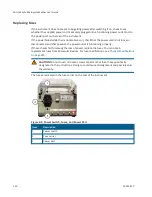
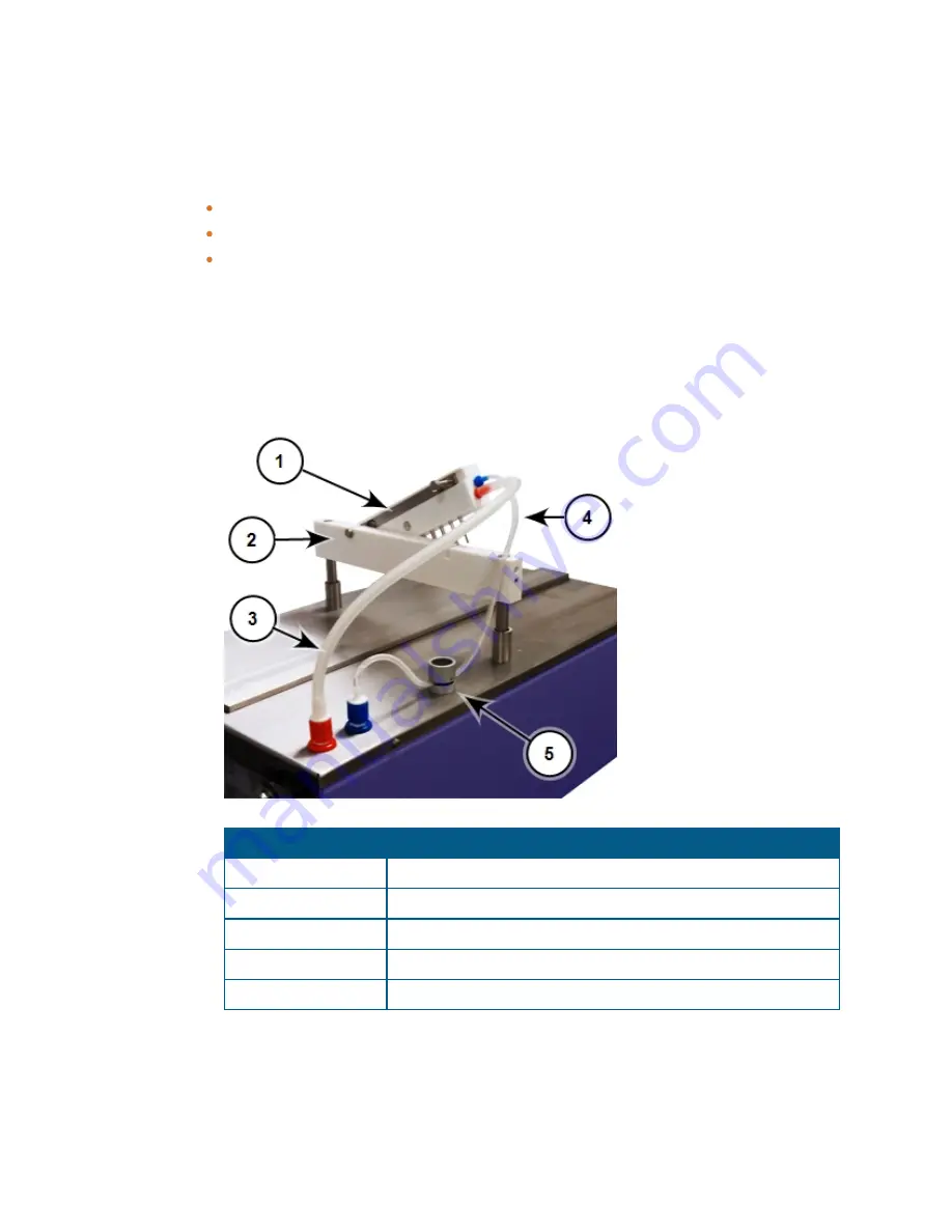
Item

Description

Manifold

Manifold holder

Aspiration tubing

Dispense tubing

Pinch valve

Figure 9-10: Manifold and Hydraulic Tubing

Содержание MultiWash+

Страница 1: ...5032022 C August 2019 MultiWash Microplate Washer User Guide ...

Страница 2: ...r license to use or permit others to use such manufacturers and or their product names as trademarks Each product is shipped with documentation stating specifications and other technical information Molecular Devices products are warranted to meet the stated specifications Molecular Devices makes no other warranties or representations express or implied including but not limited to the fitness of ...

Страница 3: ... a Microplate 24 Chapter 3 Running a Procedure 25 Running the Selected Procedure 26 Chapter 4 Priming or Rinsing the Fluidics System 31 Running a Manual Prime or Rinse Process 32 Running an Automatic Prime or Rinse Process 37 Running a Periodic Prime or Rinse Process 43 Chapter 5 Defining a Procedure 51 Defining the Procedure 52 Chapter 6 Defining a Wash or Rinse Cycle 65 Defining the Cycle 66 Cha...

Страница 4: ...g 120 Selecting the Key Click Option 121 Selecting the Emergency Stop Option 122 Chapter 9 Maintenance and Troubleshooting 123 Preventive Maintenance 123 Clean the Instrument 124 Maintaining the Fluidics System and Manifold 126 Replacing Fuses 130 Packing the Instrument for Storage or Service 132 Status Messages and Error Messages 141 Obtaining Support 142 Appendix A Parts and Accessories 143 Appe...

Страница 5: ...ied by Molecular Devices the protection provided by the equipment might be impaired Warnings Cautions Notes and Tips All warning symbols are framed within a yellow triangle An exclamation mark is used for most warnings Other symbols can warn of other types of hazards such as biohazard electrical or laser safety warnings as are described in the text of the warning Follow the related safety informat...

Страница 6: ... and Electronic Equipment WEEE Directive of the European Union It indicates that you must not discard this electrical or electronic product or its components in domestic household waste or in the municipal waste collection system For products under the requirement of the WEEE directive contact your dealer or local Molecular Devices office for the procedures to facilitate the proper collection trea...

Страница 7: ...nspect all electrical equipment before use and report all electrical deficiencies Contact Molecular Devices technical support for equipment service that requires the removal of covers or panels To prevent electrical shock use the supplied power cord and connect to a properly grounded wall outlet To ensure sufficient ventilation and provide access to disconnect power from the instrument maintain a ...

Страница 8: ...oving parts that can cause injury Under normal conditions the instrument is designed to protect you from these moving parts WARNING If the instrument is used in a manner not specified by Molecular Devices the protection provided by the equipment might be impaired To prevent injury Never try to exchange labware reagents or tools while the instrument is operating Never try to physically restrict the...

Страница 9: ... rear of the instrument and the wall Keep the instrument away from direct sunlight Unpacking and setting up the instrument includes the following procedures Unpacking the instrument and saving the original packaging See Unpacking the Washer on page 11 Installing the manifold and connecting the fluidics tubing See Installing the Manifold on page 15 Connecting the fluidics tubing to the waste rinse ...

Страница 10: ...are required for installing the instrument as follows MultiWash Microplate Washer Quick Start Guide MultiWash Microplate Washer Power cord 2 5 L waste bottle 2 0 L rinse bottle 2 0 L wash bottles 3 Microplate carrier 8 channel manifold Fluidics tubing Cleaning tools for manifold needles Spare fuses 2 Figure 1 1 Instrument and Accessories ...

Страница 11: ...se tools that can damage the packaging or the instrument To unpack the washer 1 Check the box for visible damage that occurred during transportation In case of damage immediately report it to your Molecular Devices representative and keep the damaged packaging 2 With the box facing up as indicated on the packaging use a box cutter to carefully cut open the top of the box 3 Remove the power cable 4...

Страница 12: ...MicroWash Microplate Washer User Guide 12 5032022 C 5 Remove the accessories boxes Figure 1 3 Accessories Boxes 6 Remove the cardboard dividers from each end of the box Figure 1 4 Cardboard Dividers ...

Страница 13: ... 00 cm 18 11 in deep To provide access to disconnect power from the instrument maintain a 20 cm to 30 cm 7 9 in to 11 8 in gap between the rear of the instrument and the wall Keep the instrument away from direct sunlight 11 Visually inspect the instrument for loose bent or broken parts If damage is found immediately report it to your Molecular Devices representative 12 Compare the serial number on...

Страница 14: ...s 16 Remove the metal microplate carrier lock that is attached to the instrument deck with adhesive tape and held in place by the magnet below the surface of the instrument 17 Keep the shipping box and all packaging materials for future transport needs CAUTION Before the instrument is installed and powered on let the instrument stand for at least 2 hours to reduce the possibility of condensation t...

Страница 15: ...t orientation The instrument comes with the standard 8 channel manifold The standard manifold and the fluidics tubing for connecting the manifold to the instrument are packed in separate accessories boxes To install the manifold 1 Open the clear cover 2 Connect the red quick fit connector on the aspiration tubing to the red connector on the top of the instrument Item Description 1 Manifold 2 Manif...

Страница 16: ...r on the manifold Note Make sure that there is enough slack in the dispense tubing on both sides of the pinch valve to allow for vertical movement of the manifold and to allow fluid to flow freely through the tubing 8 Place the manifold on the horizontal manifold holder with the needles pointing down and the mounting pins pointing to the rear of the instrument Figure 1 9 Placing the Manifold on th...

Страница 17: ...o the instrument The bottles and fittings are labeled for their intended use For example the 2 liter rinse bottle is labeled Rinse and the corresponding fitting on the rear of the instrument is also labeled Rinse To install the fluid bottles 1 Locate the waste tubing with the red marking 2 Connect the waste tubing to the Waste fitting framed in red on the rear of the instrument 3 Connect the other...

Страница 18: ...trong magnet permanently mounted to its base When the microplate carrier is removed from the instrument keep the carrier away from magnet sensitive items or devices Before installing the microplate carrier for the first time remove all packing materials and adhesive tape from the microplate carrier and make sure that the metal microplate carrier lock has been removed from the instrument deck To in...

Страница 19: ...ed power cord into the power port 3 Plug the other end of the power cord into a properly grounded electrical wall outlet 4 Make sure that the instrument is in position for operation on the work bench CAUTION Before turning on the power to the instrument make sure that the metal microplate carrier lock has been removed from the instrument deck and that the microplate carrier is installed 5 Turn on ...

Страница 20: ...MicroWash Microplate Washer User Guide 20 5032022 C ...

Страница 21: ... control all instrument operations using the 5 keys and the 2 line LCD display on the front of the instrument Using the on board software you can save up to 50 user defined procedures Each procedure can run 1 to 8 cycles selected from a list of up to 20 user defined cycles You can save up to 20 user defined microplate types to use with your procedures The movement of the microplate and manifold ca...

Страница 22: ...buttons below the display correspond with the functions in the second line of the display The two buttons correspond to the functions displayed directly above them in the second line of the display The functionality assigned to these buttons changes depending on the needs of the command in the first line of the display For example from a top level menu press these buttons to scroll through the oth...

Страница 23: ... define and save procedures using defined cycles and defined microplate types See Defining a Procedure on page 51 From Define Cycle define and save wash or rinse cycles to be used in procedure definitions See Defining a Wash or Rinse Cycle on page 65 From Define Plate define and save microplate types to be used in procedure definitions See Defining a Microplate Type on page 77 From Setup customize...

Страница 24: ...oading a Microplate A microplate can be loaded into the microplate carrier in either portrait or landscape orientation depending on the installed manifold The standard 8 channel manifold works with 96 well plates in portrait orientation The optional 12 channel manifold works with 96 well plates in landscape orientation The optional 16 channel manifold works with 384 well plates in portrait orienta...

Страница 25: ... have one or more procedures defined scroll the LCD display to Run Procedure From Run Procedure select a previously defined wash or rinse procedure from the list Figure 3 1 The Run Procedure menu option Button Action On the left Press this button to scroll to Service The Service menu is intended to be used by Molecular Devices trained personnel only On the right Press this button to scroll to Prim...

Страница 26: ...t the applicable wash and rinse bottles contain adequate liquid and that the waste bottle is empty The software displays the optional prompts in the following order 1 Confirm the Level of the Wash Bottle see page 27 2 Confirm the Level of the Waste Bottle see page 28 3 Confirm That the Microplate is Loaded see page 29 4 Define the Number of Strips to Process see page 30 If no options have been ena...

Страница 27: ... Selecting Instrument Set Up Options on page 113 Figure 3 2 The Wash Liquid OK prompt Button Action On the left If the wash bottle does not contain enough liquid press this button to return to Run Procedure See Running a Procedure on page 25 On the right If the wash bottle contains enough liquid press this button to go to the next step If no other options have been enabled then the selected proced...

Страница 28: ...on in the Setup menu see Selecting Instrument Set Up Options on page 113 Figure 3 3 The Waste Empty prompt Button Action On the left If the waste bottle is not empty press this button to return to Run Procedure See Running a Procedure on page 25 On the right If the waste bottle is empty press this button to go to the next step If no other options have been enabled then the selected procedure start...

Страница 29: ...able the Plate Warning option in the Setup menu see Selecting Instrument Set Up Options on page 113 Figure 3 4 The Plate Inserted prompt Button Action On the left If the microplate has not been loaded into the microplate carriage press this button to return to Run Procedure See Running a Procedure on page 25 On the right If the microplate has been loaded into the microplate carriage press this but...

Страница 30: ...er of Strips prompt Button Action On the left Press this button to return to Run Procedure See Running a Procedure on page 25 On the right The button has no function for this option Press this button to reduce the number of strips to process Press this button to increase the number of strips to process Press this button to confirm the number of strips to process and then start to run the selected ...

Страница 31: ...epeatedly at a specified interval of time See Running a Periodic Prime or Rinse Process on page 43 Figure 4 1 The Prime Rinse menu option Button Action On the left Press this button to scroll to Run Procedure See Running a Procedure on page 25 On the right Press this button to scroll to Define Procedure See Defining a Procedure on page 51 Press this button to scroll forward through the list of pri...

Страница 32: ...ty The minimum volume required for a Prime Rinse function is 7 5mL 1 5mL total of 9mL where 7 5mL is the volume of liquid in the tube from Rinse bottle to Dispense head of manifold and 1 5mL is the volume dispensed during the Prime Rinse cycle We suggest using a little more than 7 5mL 1 5mL to have enough backup pressure to push liquid through the tube and dispense the required volume 1 5mL The so...

Страница 33: ...s and return to Prime Rinse See Priming or Rinsing the Fluidics System on page 31 On the right The button has no function for this option Press this button to scroll forward through the list of wash and rinse bottles Press this button to scroll backward through the list of wash and rinse bottles Press this button to confirm the bottle selection and go to the next step The software displays a serie...

Страница 34: ...re than 7 5mL 1 5mL to have enough backup pressure to push liquid through the tube and dispense the required volume 1 5mL To enable the Liquid Warning option in the Setup menu see Selecting Instrument Set Up Options on page 113 Figure 4 5 The Wash Liquid OK prompt Button Action On the left If the wash or rinse bottle does not contain enough liquid press this button to return to Prime Rinse See Pri...

Страница 35: ...spensed during the Prime Rinse cycle We suggest using a little more than 7 5mL 1 5mL to have enough backup pressure to push liquid through the tube and dispense the required volume 1 5mL To enable the Waste Warning option in the Setup menu see Selecting Instrument Set Up Options on page 113 Figure 4 6 The Waste Empty prompt Button Action On the left If the waste bottle is not empty press this butt...

Страница 36: ...e left Press this button to end the process and return to Prime Rinse See Priming or Rinsing the Fluidics System on page 31 On the right Press and hold this button down for as long as you want the prime or rinse process to run To stop the process release the button The button has no function for this option The button has no function for this option The button has no function for this option Table...

Страница 37: ...a Prime Rinse function is 7 5mL 1 5mL total of 9mL where 7 5mL is the volume of liquid in the tube from Rinse bottle to Dispense head of manifold and 1 5mL is the volume dispensed during the Prime Rinse cycle We suggest using a little more than 7 5mL 1 5mL to have enough backup pressure to push liquid through the tube and dispense the required volume 1 5mL The software displays the prompts in the ...

Страница 38: ...e See Priming or Rinsing the Fluidics System on page 31 On the right The button has no function for this option Press this button to scroll forward through the list of wash and rinse bottles Press this button to scroll backward through the list of wash and rinse bottles Press this button to confirm the bottle selection and go to the next step The software displays a series of optional prompts to m...

Страница 39: ... to have enough backup pressure to push liquid through the tube and dispense the required volume 1 5mL To enable the Liquid Warning option in the Setup menu see Selecting Instrument Set Up Options on page 113 Figure 4 11 The Wash Liquid OK prompt Button Action On the left If the wash or rinse bottle does not contain enough liquid press this button to return to Prime Rinse See Priming or Rinsing th...

Страница 40: ...se cycle We suggest using a little more than 7 5mL 1 5mL to have enough backup pressure to push liquid through the tube and dispense the required volume 1 5mL To enable the Waste Warning option in the Setup menu see Selecting Instrument Set Up Options on page 113 Figure 4 12 The Waste Empty prompt Button Action On the left If the waste bottle is not empty press this button to return to Prime Rinse...

Страница 41: ...d return to Prime Rinse See Priming or Rinsing the Fluidics System on page 31 On the right The button has no function for this option Press this button to increase the dispense volume by 1 mL up to a maximum of 200 mL Press this button to decrease the dispense volume by 1 mL down to a minimum of 1 mL Press this button to confirm the dispense volume and start the automatic prime or rinse process Se...

Страница 42: ...tton to end the process and return to Prime Rinse See Priming or Rinsing the Fluidics System on page 31 On the right The button has no function for this option The button has no function for this option The button has no function for this option Press this button to run the automatic prime or rinse process Table 4 10 Actions of Control Panel Buttons Figure 4 15 The Prime Rinse In Process prompt To...

Страница 43: ...the volume of liquid in the tube from Rinse bottle to Dispense head of manifold and 1 5mL is the volume dispensed during the Prime Rinse cycle We suggest using a little more than 7 5mL 1 5mL to have enough backup pressure to push liquid through the tube and dispense the required volume 1 5mL The software displays the prompts in the following order 1 Select the Bottle for the Prime or Rinse Process...

Страница 44: ...e See Priming or Rinsing the Fluidics System on page 31 On the right The button has no function for this option Press this button to scroll forward through the list of wash and rinse bottles Press this button to scroll backward through the list of wash and rinse bottles Press this button to confirm the bottle selection and go to the next step The software displays a series of optional prompts to m...

Страница 45: ...to have enough backup pressure to push liquid through the tube and dispense the required volume 1 5mL To enable the Liquid Warning option in the Setup menu see Selecting Instrument Set Up Options on page 113 Figure 4 19 The Wash Liquid OK prompt Button Action On the left If the wash or rinse bottle does not contain enough liquid press this button to return to Prime Rinse See Priming or Rinsing the...

Страница 46: ...e cycle We suggest using a little more than 7 5mL 1 5mL to have enough backup pressure to push liquid through the tube and dispense the required volume 1 5mL To enable the Waste Warning option in the Setup menu see Selecting Instrument Set Up Options on page 113 Figure 4 20 The Waste Empty prompt Button Action On the left If the waste bottle is not empty press this button to return to Prime Rinse ...

Страница 47: ...inse See Priming or Rinsing the Fluidics System on page 31 On the right The button has no function for this option Press this button to increase the dispense volume by 1 mL up to a maximum of 200 mL Press this button to decrease the dispense volume by 1 mL down to a minimum of 1 mL Press this button to confirm the dispense volume and then define the time between each periodic prime or rinse proces...

Страница 48: ...ction On the left Press this button to end the process and return to Prime Rinse See Priming or Rinsing the Fluidics System on page 31 On the right The button has no function for this option Press this button to increase the interval by 1 minute up to a maximum of 200 minutes Press this button to decrease the interval by 1 minute down to a minimum of 1 minute Press this button to confirm the inter...

Страница 49: ...inse See Priming or Rinsing the Fluidics System on page 31 On the right The button has no function for this option The button has no function for this option The button has no function for this option Press this button to run the periodic prime or rinse process Table 4 16 Actions of Control Panel Buttons Figure 4 24 The Periodic Rinse prompt The defined prime or rinse process repeats after the def...

Страница 50: ...MicroWash Microplate Washer User Guide 50 5032022 C ...

Страница 51: ...by editing an existing procedure and giving it a new name Figure 5 1 The Define Procedure menu option Button Action On the left Press this button to scroll to Prime Rinse See Priming or Rinsing the Fluidics System on page 31 On the right Press this button to scroll to Define Cycle See Defining a Wash or Rinse Cycle on page 65 Press this button to scroll forward through the list of previously defin...

Страница 52: ...oplate Type on page 77 The software displays the prompts for the procedure definition in the following order 1 Confirm or Change the Name of the Procedure see page 53 2 Select the Bottle for the Procedure see page 55 3 Select the Cycles for the Procedure see page 56 4 Select the Duration of the Final Aspiration for the Procedure see page 58 5 Select the Speed of the Final Aspiration for the Proced...

Страница 53: ...urn to Define Procedure without saving any changes See Defining a Procedure on page 51 On the right Press this button to edit the name of the procedure See Edit the Name of the Procedure on page 54 The button has no function for this option The button has no function for this option Press this button to confirm the name as it is displayed and then define the wash or rinse bottle to use for the pro...

Страница 54: ...ges See Defining a Procedure on page 51 On the right Press this button to select the character displayed on the far right side of the line Press this button to scroll forward through the available characters A to Z and 0 to 9 Press this button to scroll backward through the available characters 9 to 0 and Z to A Press this button to confirm the name as it is displayed and then define the wash or r...

Страница 55: ... return to the previous step See Confirm or Change the Name of the Procedure on page 53 On the right Press this button to end the process and return to Define Procedure without saving any changes See Defining a Procedure on page 51 Press this button to scroll forward through the list of wash and rinse bottles Press this button to scroll backward through the list of wash and rinse bottles Press thi...

Страница 56: ... left Press this button to return to the previous step See Select the Bottle for the Procedure on page 55 On the right Press this button to end the process and return to Define Procedure without saving any changes See Defining a Procedure on page 51 Press this button to scroll forward through the list of previously defined cycles Press this button to scroll backward through the list of previously ...

Страница 57: ...ing any changes See Defining a Procedure on page 51 Press this button to scroll forward through the list of previously defined cycles When you have finished adding cycles select to stop adding cycles to the procedure definition Press this button to scroll backward through the list of previously defined cycles When you have finished adding cycles select to stop adding cycles to the procedure defini...

Страница 58: ...the previous step See Select the Cycles for the Procedure on page 56 On the right Press this button to end the process and return to Define Procedure without saving any changes See Defining a Procedure on page 51 Press this button to add time to the duration in 0 1 second intervals to a maximum of 10 0 seconds Press this button to subtract time from the duration in 0 1 second intervals to a minimu...

Страница 59: ... the Procedure on page 58 On the right Press this button to end the process and return to Define Procedure without saving any changes See Defining a Procedure on page 51 Press this button to scroll forward through the aspiration speeds Low Medium or High Press this button to scroll backward through the aspiration speeds High Medium or Low Press this button to confirm the speed and then select the ...

Страница 60: ... Aspiration for the Procedure on page 59 On the right Press this button to end the process and return to Define Procedure without saving any changes See Defining a Procedure on page 51 Press this button to display either Plate or Strip Press this button to display either Plate or Strip Press this button to select the displayed mode and then select a previously defined microplate type to use with t...

Страница 61: ...step See Select the Processing Mode for the Procedure on page 60 On the right Press this button to end the process and return to Define Procedure without saving any changes See Defining a Procedure on page 51 Press this button to scroll forward through the list of previously defined microplate types Press this button to scroll backward through the list of previously defined microplate types Press ...

Страница 62: ...right Press this button to end the process and return to Define Procedure without saving any changes See Defining a Procedure on page 51 Press this button to display either Yes to enable the prompt or No to disable the prompt Press this button to display either Yes to enable the prompt or No to disable the prompt Press this button to accept the selection If you selected Plate as the processing mod...

Страница 63: ...n page 62 On the right Press this button to end the process and return to Define Procedure without saving any changes See Defining a Procedure on page 51 Press this button to display either Yes or No Select Yes to delay the final aspiration until after the last cycle for the last strip is complete and the soak time has expired Press this button to display either Yes or No Select Yes to delay the f...

Страница 64: ...MicroWash Microplate Washer User Guide 64 5032022 C ...

Страница 65: ... new cycle by editing an existing cycle and giving it a new name Figure 6 1 The Define Cycle menu option Button Action On the left Press this button to scroll to Define Procedure See Defining a Procedure on page 51 On the right Press this button to scroll to Define Plate See Defining a Microplate Type on page 77 Press this button to scroll forward through the list of previously defined cycles If y...

Страница 66: ...ge 67 2 Select the Duration of the Aspiration for the Cycle see page 69 3 Select the Speed of the Aspiration for the Cycle see page 70 4 Define the Dispense Volume for the Cycle see page 71 5 Select the Dispense Speed for the Cycle see page 72 6 Select the Wash Mode for the Cycle see page 73 7 Define the Microplate Shake Time for the Cycle see page 74 8 Select the Microplate Shake Intensity for th...

Страница 67: ...n to Define Cycle without saving any changes See Defining a Wash or Rinse Cycle on page 65 On the right Press this button to edit the name of the cycle See Edit the Name of the Cycle on page 68 The button has no function for this option The button has no function for this option Press this button to confirm the name as it is displayed and then define the aspiration duration for the cycle See Selec...

Страница 68: ...ing a Wash or Rinse Cycle on page 65 On the right Press this button to select the character displayed on the far right side of the line Press this button to scroll forward through the available characters A to Z and 0 to 9 Press this button to scroll backward through the available characters 9 to 0 and Z to A Press this button to confirm the name as it is displayed and then define the aspiration d...

Страница 69: ...previous step See Confirm or Change the Name of the Cycle on page 67 On the right Press this button to end the process and return to Define Cycle without saving any changes See Defining a Wash or Rinse Cycle on page 65 Press this button to add time to the duration in 1 second intervals to a maximum of 10 seconds Press this button to subtract time from the duration in 1 second intervals to a minimu...

Страница 70: ...ycle on page 69 On the right Press this button to end the process and return to Define Cycle without saving any changes See Defining a Wash or Rinse Cycle on page 65 Press this button to scroll forward through the aspiration speeds Low Medium or High Press this button to scroll backward through the aspiration speeds High Medium or Low Press this button to confirm the speed and then define the disp...

Страница 71: ...e Cycle on page 70 On the right Press this button to end the process and return to Define Cycle without saving any changes See Defining a Wash or Rinse Cycle on page 65 Press this button to add volume in 50 µL increments to a maximum of 2000 µL Press this button to subtract volume in 50 µL increments to a minimum of 0 µL Press this button to confirm the volume and then define the speed of the disp...

Страница 72: ... on page 71 On the right Press this button to end the process and return to Define Cycle without saving any changes See Defining a Wash or Rinse Cycle on page 65 Press this button to scroll forward through the dispense speeds Low Medium or High Press this button to scroll backward through the dispense speeds High Medium or Low Press this button to confirm the speed and then define the wash mode fo...

Страница 73: ...mends that you use a dispense volume that is slightly more than the well volume For information on defining the Bottom and Overflow positions for a microplate see Defining a Microplate Type on page 77 Figure 6 8 The Wash Mode prompt Button Action On the left Press this button to return to the previous step See Select the Dispense Speed for the Cycle on page 72 On the right Press this button to end...

Страница 74: ...ss this button to end the process and return to Define Cycle without saving any changes See Defining a Wash or Rinse Cycle on page 65 Press this button to add time to the shake duration in 1 second intervals to a maximum of 10 seconds Press this button to subtract time from the shake duration in 1 second intervals to a minimum of 0 seconds Press this button to confirm the shake duration and then d...

Страница 75: ...Cycle on page 74 On the right Press this button to end the process and return to Define Cycle without saving any changes See Defining a Wash or Rinse Cycle on page 65 Press this button to scroll forward through the shake speeds Low Medium or High Press this button to scroll backward through the shake speeds High Medium or Low Press this button to confirm the shake intensity and then define the min...

Страница 76: ...ake Intensity for the Cycle on page 75 On the right Press this button to end the process and return to Define Cycle without saving any changes See Defining a Wash or Rinse Cycle on page 65 Press this button to add time to the minimum soak duration in 10 second intervals to a maximum of 1000 seconds Press this button to subtract time from the shake duration in 10 second intervals to a minimum of 0 ...

Страница 77: ...ting microplate type and giving it a new name Figure 7 1 The Define Plate menu option Button Action On the left Press this button to scroll to Define Cycle See Defining the Cycle on page 66 On the right Press this button to scroll to Setup See Selecting Instrument Set Up Options on page 113 Press this button to scroll forward through the list of previously defined microplate types If you want to e...

Страница 78: ...d bottom and flat bottom microplates For round bottom microplates define the center of the well for aspiration Item Description 1 Dispense needle 2 Aspiration needle 3 Vertical zero point for setting the vertical position of the manifold 4 Horizontal zero point for setting the horizontal position of the microplate Table 7 2 Round Bottom Microplate To define a round bottom microplate type see Defin...

Страница 79: ... needle 2 Aspiration needle 3 Vertical zero point for setting the vertical position of the manifold 4 Horizontal zero point for setting the horizontal position of the microplate Table 7 3 Flat Bottom Microplate Note Crosswise aspiration is available only for flat bottom microplates To define a flat bottom microplate type see Defining a Flat Bottom Microplate Type on page 95 ...

Страница 80: ...type scroll until new is displayed Press to start defining the microplate type The software displays the prompts for defining the microplate type in the following order 1 Confirm or Change the Name of the Microplate Type see page 81 2 Select the Format of the Microplate Type see page 83 3 Select the Well Shape of the Microplate Type see page 84 4 Define the Center of the Well for Aspiration see pa...

Страница 81: ...d the process and return to Define Plate without saving any changes See Defining a Microplate Type on page 77 On the right Press this button to edit the name of the cycle See Edit the Name of the Microplate Type on page 82 The button has no function for this option The button has no function for this option Press this button to confirm the name as it is displayed and then define the microplate for...

Страница 82: ...ing any changes See Defining a Microplate Type on page 77 On the right Press this button to select the character displayed on the far right side of the line Press this button to scroll forward through the available characters A to Z and 0 to 9 Press this button to scroll backward through the available characters 9 to 0 and Z to A Press this button to confirm the name as it is displayed and then de...

Страница 83: ...5 The Plate Format prompt Button Action On the left Press this button to return to the previous step See Confirm or Change the Name of the Microplate Type on page 81 On the right Press this button to end the process and return to Define Plate without saving any changes See Defining a Microplate Type on page 77 Press this button to scroll forward through the microplate formats 8 strip 12 strip or 1...

Страница 84: ... Microplate Type on page 83 On the right Press this button to end the process and return to Define Plate without saving any changes See Defining a Microplate Type on page 77 Press this button to display either Flat or Round To define a round bottom microplate type select Round Press this button to display either Flat or Round To define a round bottom microplate type select Round Press this button ...

Страница 85: ...he left Press this button to end the process and return to Define Plate without saving any changes See Defining a Microplate Type on page 77 On the right Press this button to move the microplate to the currently saved center position and switch to teach in mode See Teach In the Center of the Well for Aspiration on page 86 Press this button to increase the offset value by 0 1 mm to a maximum of 5 0...

Страница 86: ...to the bottom of the well With displayed on the left press this button to move the manifold up On the right Press this button to move the microplate to the currently saved center position Press this button to increase the offset value by 0 1 mm to a maximum of 5 0 mm Press this button to decrease the offset value by 0 1 mm to a minimum of 5 0 mm Press this button to accept the displayed offset val...

Страница 87: ... to Define Plate without saving any changes See Defining a Microplate Type on page 77 On the right Press this button to move the microplate to the currently saved aspiration position and switch to teach in mode See Teach In the Height for Aspiration on page 88 Press this button to increase the offset value by 0 1 mm to a maximum of 18 8 mm Press this button to decrease the offset value by 0 1 mm t...

Страница 88: ...om of the well With displayed on the left press this button to move the manifold up On the right Press this button to move the microplate to the currently saved aspiration position Press this button to increase the offset value by 0 1 mm to a maximum of 18 8 mm Press this button to decrease the offset value by 0 1 mm to a minimum of 0 0 mm Press this button to accept the displayed offset value and...

Страница 89: ...mpt Button Action On the left Press this button to end the process and return to Define Plate without saving any changes See Defining a Microplate Type on page 77 On the right Press this button to move the microplate to the currently saved dispense position and switch to teach in mode See Teach In the Dispense Position on page 90 Press this button to increase the offset value by 0 1 mm to a maximu...

Страница 90: ...l With displayed on the left press this button to move the manifold up On the right Press this button to move the microplate to the currently saved dispense position Press this button to increase the offset value by 0 1 mm to a maximum of 5 0 mm Press this button to decrease the offset value by 0 1 mm to a minimum of 5 0 mm Press this button to accept the displayed offset value and then define the...

Страница 91: ...ess this button to end the process and return to Define Plate without saving any changes See Defining a Microplate Type on page 77 On the right Press this button to move the microplate to the currently saved bottom dispense position and switch to teach in mode See Teach In the Bottom Dispense Height on page 92 Press this button to increase the offset value by 0 1 mm to a maximum of 18 8 mm Press t...

Страница 92: ...m of the well With displayed on the left press this button to move the manifold up On the right Press this button to move the microplate to the currently saved bottom dispense position Press this button to increase the offset value by 0 1 mm to a maximum of 18 8 mm Press this button to decrease the offset value by 0 1 mm to a minimum of 0 0 mm Press this button to accept the displayed offset value...

Страница 93: ...ch in method Figure 7 20 The Overflow Dispense Height prompt Button Action On the left Press this button to end the process and return to Define Plate without saving any changes See Defining a Microplate Type on page 77 On the right Press this button to move the microplate to the currently saved overflow dispense position and switch to teach in mode See Teach In the Overflow Dispense Height on pag...

Страница 94: ...needle to the bottom of the well With displayed on the left press this button to move the manifold up On the right Press this button to move the microplate to the currently saved overflow dispense position Press this button to increase the offset value by 0 1 mm to a maximum of 18 8 mm Press this button to decrease the offset value by 0 1 mm to a minimum of 0 0 mm Press this button to accept the d...

Страница 95: ...g the microplate type The software displays the prompts for defining the microplate type in the following order 1 Confirm or Change the Name of the Microplate Type see page 96 2 Select the Format of the Microplate Type see page 98 3 Select the Well Shape of the Microplate Type see page 99 4 Select Whether to Use Crosswise Aspiration see page 100 5 Define the Side for Aspiration see page 101 6 Defi...

Страница 96: ...nd the process and return to Define Plate without saving any changes See Defining a Microplate Type on page 77 On the right Press this button to edit the name of the cycle See Edit the Name of the Microplate Type on page 97 The button has no function for this option The button has no function for this option Press this button to confirm the name as it is displayed and then define the microplate fo...

Страница 97: ...ng any changes See Defining a Microplate Type on page 77 On the right Press this button to select the character displayed on the far right side of the line Press this button to scroll forward through the available characters A to Z and 0 to 9 Press this button to scroll backward through the available characters 9 to 0 and Z to A Press this button to confirm the name as it is displayed and then def...

Страница 98: ...25 The Plate Format prompt Button Action On the left Press this button to return to the previous step See Confirm or Change the Name of the Microplate Type on page 96 On the right Press this button to end the process and return to Define Plate without saving any changes See Defining a Microplate Type on page 77 Press this button to scroll forward through the microplate formats 8 strip 12 strip or ...

Страница 99: ...e Microplate Type on page 98 On the right Press this button to end the process and return to Define Plate without saving any changes See Defining a Microplate Type on page 77 Press this button to display either Flat or Round To define a flat bottom microplate type select Flat Press this button to display either Flat or Round To define a flat bottom microplate type select Flat Press this button to ...

Страница 100: ...28 The Crosswise Aspiration prompt Button Action On the left Press this button to return to the previous step See Select the Well Shape of the Microplate Type on page 99 On the right Press this button to end the process and return to Define Plate without saving any changes See Defining a Microplate Type on page 77 Press this button to display either Yes or No To enable crosswise aspiration select ...

Страница 101: ...nd the process and return to Define Plate without saving any changes See Defining a Microplate Type on page 77 On the right Press this button to move the microplate to the currently saved aspiration position and switch to teach in mode See Teach In the Side for Aspiration on page 102 Press this button to increase the offset value by 0 1 mm to a maximum of 5 0 mm Press this button to decrease the o...

Страница 102: ...ove the manifold up On the right Press this button to move the microplate to the currently saved aspiration position Press this button to increase the offset value by 0 1 mm to a maximum of 5 0 mm Press this button to decrease the offset value by 0 1 mm to a minimum of 5 0 mm Press this button to accept the displayed offset value If crosswise aspiration is enabled then you can define the second si...

Страница 103: ...y using the teach in method Figure 7 33 The Side Position Rear prompt Button Action On the left Press this button to end the process and return to Define Plate without saving any changes See Defining a Microplate Type on page 77 On the right Press this button to move the microplate to the currently saved second side position and switch to teach in mode See Teach In the Second Side for Crosswise As...

Страница 104: ... needle to the bottom of the well With displayed on the left press this button to move the manifold up On the right Press this button to move the microplate to the currently saved second side position Press this button to increase the offset value by 0 1 mm to a maximum of 5 0 mm Press this button to decrease the offset value by 0 1 mm to a minimum of 5 0 mm Press this button to accept the display...

Страница 105: ...fine Plate without saving any changes See Defining a Microplate Type on page 77 On the right Press this button to move the microplate to the currently saved aspiration position and switch to teach in mode See Teach In the Center of the Well for Aspiration on page 86 Press this button to increase the offset value by 0 1 mm to a maximum of 18 8 mm Press this button to decrease the offset value by 0 ...

Страница 106: ...om of the well With displayed on the left press this button to move the manifold up On the right Press this button to move the microplate to the currently saved aspiration position Press this button to increase the offset value by 0 1 mm to a maximum of 18 8 mm Press this button to decrease the offset value by 0 1 mm to a minimum of 0 0 mm Press this button to accept the displayed offset value and...

Страница 107: ...pt Button Action On the left Press this button to end the process and return to Define Plate without saving any changes See Defining a Microplate Type on page 77 On the right Press this button to move the microplate to the currently saved dispense position and switch to teach in mode See Teach In the Dispense Position on page 108 Press this button to increase the offset value by 0 1 mm to a maximu...

Страница 108: ...l With displayed on the left press this button to move the manifold up On the right Press this button to move the microplate to the currently saved dispense position Press this button to increase the offset value by 0 1 mm to a maximum of 5 0 mm Press this button to decrease the offset value by 0 1 mm to a minimum of 5 0 mm Press this button to accept the displayed offset value and then define the...

Страница 109: ...ess this button to end the process and return to Define Plate without saving any changes See Defining a Microplate Type on page 77 On the right Press this button to move the microplate to the currently saved bottom dispense position and switch to teach in mode See Teach In the Bottom Dispense Height on page 110 Press this button to increase the offset value by 0 1 mm to a maximum of 18 8 mm Press ...

Страница 110: ...m of the well With displayed on the left press this button to move the manifold up On the right Press this button to move the microplate to the currently saved bottom dispense position Press this button to increase the offset value by 0 1 mm to a maximum of 18 8 mm Press this button to decrease the offset value by 0 1 mm to a minimum of 0 0 mm Press this button to accept the displayed offset value...

Страница 111: ...ch in method Figure 7 45 The Overflow Dispense Height prompt Button Action On the left Press this button to end the process and return to Define Plate without saving any changes See Defining a Microplate Type on page 77 On the right Press this button to move the microplate to the currently saved overflow dispense position and switch to teach in mode See Teach In the Overflow Dispense Height on pag...

Страница 112: ...needle to the bottom of the well With displayed on the left press this button to move the manifold up On the right Press this button to move the microplate to the currently saved overflow dispense position Press this button to increase the offset value by 0 1 mm to a maximum of 18 8 mm Press this button to decrease the offset value by 0 1 mm to a minimum of 0 0 mm Press this button to accept the d...

Страница 113: ...n to scroll to Define Plate See Defining a Microplate Type on page 77 On the right Press this button to scroll to Service The Service menu is intended to be used by Molecular Devices trained personnel only The button has no function for this option The button has no function for this option Press this button to start defining the set up options with the language selection See Selecting the Languag...

Страница 114: ... Press this button to return to Setup See Selecting Instrument Set Up Options on page 113 On the right The button has no function for this option Press this button to display either English or German Press this button to display either English or German Press this button to select the language and then define the installed manifold See Selecting the Installed Manifold on page 115 Table 8 2 Actions...

Страница 115: ...tional 16 channel manifold works with 384 well plates in portrait orientation Figure 8 3 The Manifold option Button Action On the left Press this button to return to Language See Selecting the Language for the Display on page 114 On the right Press this button to return to Setup See Selecting Instrument Set Up Options on page 113 Press this button to scroll forward through the list of available ma...

Страница 116: ...led Manifold on page 115 On the right Press this button to return to Setup See Selecting Instrument Set Up Options on page 113 Press this button to scroll forward through the number of wash bottles 1 2 or 3 Press this button to scroll forward through the number of wash bottles 3 2 or 1 Press this button to select the number of wash bottles and then scroll through the detection options See Scrollin...

Страница 117: ...tion Press to go to the Rinse Empty Detection option Figure 8 6 The Rinse Empty Detection option Press to go to the Wash1 Empty Detection option Figure 8 7 The Wash1 Empty Detection option Press to go to the Wash2 Empty Detection option Figure 8 8 The Wash2 Empty Detection option Press to go to the Wash2 Empty Detection option Figure 8 9 The Wash3 Empty Detection option Press to set the liquid lev...

Страница 118: ...Warning option Button Action On the left Press this button to return to Wash3 Empty Detection See Scrolling Through the Detection Options on page 117 On the right Press this button to return to Setup See Selecting Instrument Set Up Options on page 113 Press this button to display either On or Off Press this button to display either On or Off Press this button to confirm the selection and then set ...

Страница 119: ... the left Press this button to return to Liquid Warning See Selecting the Display of the Liquid Level Warning on page 118 On the right Press this button to return to Setup See Selecting Instrument Set Up Options on page 113 Press this button to display either On or Off Press this button to display either On or Off Press this button to confirm the selection and then set the microplate warning messa...

Страница 120: ...ption Button Action On the left Press this button to return to Waste Warning See Selecting the Display of the Waste Level Warning on page 119 On the right Press this button to return to Setup See Selecting Instrument Set Up Options on page 113 Press this button to display either On or Off Press this button to display either On or Off Press this button to confirm the selection and then set the key ...

Страница 121: ...ing See Selecting the Display of the Microplate Warning on page 120 On the right Press this button to return to Setup See Selecting Instrument Set Up Options on page 113 Press this button to display either On or Off Press this button to display either On or Off Press this button to confirm the selection and then set the emergency stop option See Selecting the Emergency Stop Option on page 122 Tabl...

Страница 122: ... option Button Action On the left Press this button to return to Key Click See Selecting the Key Click Option on page 121 On the right Press this button to return to Setup See Selecting Instrument Set Up Options on page 113 Press this button to display either On or Off Press this button to display either On or Off Press this button to confirm the selection and then return to Setup See Selecting In...

Страница 123: ... the Instrument see page 124 Maintaining the Fluidics System and Manifold see page 126 Replacing Fuses see page 130 Packing the Instrument for Storage or Service see page 132 Status Messages and Error Messages see page 141 CAUTION Maintenance procedures other than those specified in this guide must be performed by Molecular Devices When service is required contact Molecular Devices technical suppo...

Страница 124: ...ter and then wipe with a damp cloth or sponge to remove all residue Other recommended cleaning solutions include a 70 ethanol solution a 2 SDS sodium dodecylsulphate solution or a 4 glutaraldehyde solution Clean the area around the microplate carrier with a dry lint free cloth The microplate carrier can be removed from the instrument to clean the carrier and the surrounding area After all metal su...

Страница 125: ...rfaces and the microplate carrier using a cloth or sponge that has been lightly dampened with the disinfectant solution To remove the disinfectant residue wipe the outside surfaces and the microplate carrier using a cloth or sponge that has been lightly dampened with a 50 alcohol solution and then wipe again using a cloth or sponge that has been lightly dampened with water After all metal surfaces...

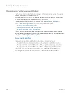
Страница 126: ...fold Needles see page 129 Replacing the Fluidics Tubing see page 129 Perform only the maintenance tasks described in this guide Contact a Molecular Devices service engineer to inspect and perform a preventive maintenance service on the instrument each year See Obtaining Support on page 142 Replacing the Manifold There are three manifolds available for the MultiWash Microplate Washer The standard 8...

Страница 127: ...ke sure that the dispense tube remains in the pinch valve on the top of the instrument Item Description 1 Manifold 2 Manifold holder 3 Aspiration tubing 4 Dispense tubing 5 Pinch valve Figure 9 1 Manifold and Hydraulic Tubing 4 Remove the aspiration tube from the red connector on the manifold 5 Lift the manifold off the horizontal manifold holder and set the manifold aside ...

Страница 128: ...nifold holder 8 Slide the aspiration tube onto the red connector on the manifold 9 Slide the dispense tube onto the blue connector on the manifold Note Make sure that there is enough slack in the dispense tubing on both sides of the pinch valve to allow for vertical movement of the manifold and to allow fluid to flow freely through the tubing 10 Close the clear cover After you start the instrument...

Страница 129: ...ning Slide the pin into the manifold needles to clear blockages Figure 9 4 Cleaning the Manifold Needles Replacing the Fluidics Tubing Fluidics tubing connect the bottles to the rear of the instrument and the manifold to the top of the instrument Periodically inspect the fluidics tubing for cracks or leaks Replace the tubing as needed For information about connecting the fluidics tubing to the bot...

Страница 130: ... and that power to the power outlet is functioning properly If these checks fail to remedy the loss of power replace the fuses You can obtain replacement fuses from Molecular Devices For fuse specifications see Physical Specifications on page 145 CAUTION Do not touch or loosen screws or parts other than those specifically designated in the instructions Doing so could cause misalignment and possibl...

Страница 131: ...ead screwdriver below the fuse carrier and gently pry the fuse carrier from the instrument 4 Gently pull the old fuses from the carrier by hand Figure 9 6 Fuse Carrier 5 Gently place new fuses into the carrier by hand 6 Return the fuse carrier to the slot above the power port with the tabs on the carrier pointing down 7 Press the fuse carrier into the instrument until the carrier snaps into place ...

Страница 132: ...ean the Instrument on page 124 CAUTION When transporting the instrument warranty claims are void if improper packing results in damage to the instrument Store the instrument in a dry dust free environmentally controlled area Packing the instrument includes the following procedures Disconnecting Power From the Instrument see page 133 Removing the Microplate Carrier see page 134 Disconnecting the Fl...

Страница 133: ...cription 1 Power switch 2 Fuse carrier 3 Power port Figure 9 7 Power Switch Fuses and Power Port To disconnect power from the instrument 1 Make sure that the power switch on the rear of the instrument is in the off position 2 Unplug the power cord from the electrical wall outlet 3 Unplug the power cord from the power port on the rear of the instrument 4 Set the power cord aside ...

Страница 134: ...ery strong magnet permanently mounted to its base When the microplate carrier is removed from the instrument keep the carrier away from magnet sensitive items or devices Figure 9 8 Installed Microplate Carrier To remove the microplate carrier carefully slide it off the front of the instrument Set the microplate carrier aside ...

Страница 135: ...ittings with the blue labels below them on the rear of the instrument 2 Disconnect the other end of the wash tubing from the fittings on top of the 2 liter wash bottles 3 Disconnect the rinse tubing from the rinse fitting with the black label below it on the rear of the instrument 4 Disconnect the other end of the rinse tubing from the fitting on top of the 2 liter rinse bottle 5 Disconnect the wa...

Страница 136: ...l 16 channel manifold works with 384 well plates in portrait orientation The instrument comes with the standard 8 channel manifold The fluidics tubing for connecting the manifold to the instrument is packed with the standard manifold Other manifolds are packed separately To remove the manifold and fluidics tubing 1 Open the clear cover 2 Remove the dispense tubing from the blue connector on the ma...

Страница 137: ...nse tubing into an appropriate receptacle and then set the dispense tubing aside 6 Remove the aspiration tubing from the red connector on the manifold 7 Disconnect the red quick fit connector on the aspiration tubing from the red connector on the top of the instrument 8 Drain the aspiration tubing into an appropriate receptacle and then set the aspiration tubing aside 9 Lift the manifold off the h...

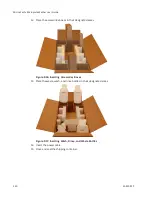
Страница 138: ...lts in damage to the instrument Make sure that the instrument is clean and dry before packing To pack the instrument 1 Pack the microplate carrier manifold and fluidics tubing in their original boxes Figure 9 12 Packing the Accessories Boxes 2 Open the clear cover 3 Place the metal microplate carrier lock to the left of the rail on the top of the instrument Figure 9 13 Installing the Microplate Ca...

Страница 139: ...e the cardboard packing sheet on top of the clear cover with the foam resting against the rear of the cover and then secure it with adhesive tape Figure 9 14 Packing the Instrument 9 Place the fitted packing foam on the sides of the instrument 10 Carefully place the instrument in the center of the shipping container 11 Place the cardboard dividers in the shipping container Figure 9 15 Inserting Ca...

Страница 140: ...ccessories boxes in their designated areas Figure 9 16 Inserting Accessories Boxes 13 Place the waste wash and rinse bottles in their designated areas Figure 9 17 Inserting Wash Rinse and Waste Bottles 14 Insert the power cable 15 Close and seal the shipping container ...

Страница 141: ... procedure does not have a cycle defined You must define the cycle before you can define and run the procedure See Defining a Wash or Rinse Cycle on page 65 When the No plate defined message is displayed the selected procedure does not have a microplate type defined You must define the microplate type before you can define and run the procedure See Defining a Microplate Type on page 77 When the Pl...

Страница 142: ...o Molecular Devices Technical Support You can contact your local representative or Molecular Devices Technical Support at 800 635 5577 North America only or 1 408 747 1700 In Europe call 44 0 118 944 8000 To find regional support contact information visit www moleculardevices com contact Please have your instrument serial number or Work Order number and your software version number available when ...

Страница 143: ...h Microplate Washer Part Number Description 5032337 8 channel manifold 5032336 12 channel manifold 5032338 16 channel manifold 5032339 Washer maintenance kit 5032340 External tubing kit 5032341 2 liter wash bottle 5032342 2 liter rinse bottle Table A 1 Parts and Accessories To order parts and accessories contact your Molecular Devices representative A ...

Страница 144: ...MicroWash Microplate Washer User Guide 144 5032022 C ...

Страница 145: ... 6 20 kg 13 67 lbs Power disconnect clearance rear 20 cm to 30 cm 7 9 in to 11 8 in between the rear of the instrument and the wall Ambient operating temperature 15 C to 40 C 59 F to 104 F Ambient storage temperature 20 C to 50 C 4 F to 122 F Humidity restrictions 15 to 85 non condensing Altitude restrictions Up to 2000 m 6562 ft Sound pressure level maximum 65 dB Installation category II Pollutio...

Страница 146: ...measurement specifications of the MultiWash Microplate Washer Item Description Dispense volume The wash liquid volume is adjustable from 50 µl to 2000 µl in 50 µl increments Dispensing accuracy 5 at 300 µl across the microplate Residual volume 1 µl per well Table B 2 Measurement Specifications of the Instrument ...

Страница 147: ... C System Dimensions In the following drawings the dimensions are shown in centimeters and inches Item Description 1 Width 21 00 cm 8 27 in 2 Height 21 00 cm 8 27 in Figure C 1 Front View of the Instrument with Dimensions C ...

Страница 148: ...MicroWash Microplate Washer User Guide 148 5032022 C Item Description 1 Depth 46 00 cm 18 11 in 2 Height 21 00 cm 8 27 in Figure C 2 Side View of the Instrument with Dimensions ...

Страница 149: ... cycle7 57 cycle8 57 D decontamination 125 define cycle 23 65 define plate 23 77 80 95 define procedure 23 51 delay final aspiration 63 disinfection 125 dispense position 89 107 dispense power 72 dispense volume 71 E emergency stop 122 error messages 141 F final aspiration speed 59 final aspiration time 58 fluidics system maintenance 126 I instrument control panel 22 disinfection 125 manifold 136 ...

Страница 150: ...rrier 18 flat bottom 78 loading 24 round bottom 78 minimum soak time 76 N name 53 67 81 96 needles 129 number of strips 30 O ordering information 143 overflow dispense height 93 111 P packing instrument 132 parts ordering 143 periodic rinse 49 plate 61 plate format 83 98 plate inserted 29 plate warning 120 power switch 19 prime rinse 23 32 37 43 prime rinse in process 42 processing mode 60 R rinse...

Страница 151: ...ions instrument measurements 146 start prime rinse 42 49 start the instrument 19 status messages 141 T top level menus 23 U unpacking 11 V volume 41 47 W wash liquid OK 27 34 39 45 wash liquids 116 wash mode 73 waste empty 28 35 40 46 waste warning 119 well shape 84 99 ...

Страница 152: ...rty of Molecular Devices LLC or their respective owners Specifications subject to change without notice Patents www moleculardevices com productpatents FOR RESEARCH USE ONLY NOT FOR USE IN DIAGNOSTIC PROCEDURES 2019 Molecular Devices LLC All rights reserved 5032022 C ...

Отзывы: