background image

0112-0109 H

273 

B

Data Processing Algorithms

This appendix uses results of a hypothetical experiment to describe the 

algorithms that can be used to adjust data. These options are all 

applied from the Correction dialog. 

Hypothetical Experiment 

Consider the results from an experiment consisting of wells A1–A9. The 

wells are classified into three groups: 

A1–A3: Negative Control Wells (–Ctrl). These wells contain the 

same dye-loaded cells and buffers as the other wells, yet are not 

exposed to a stimulus. 

A4–A6: Experimental Wells (Exp). These cells receive the 

experimental stimulus. 

A7–A9: Positive Control Wells. (+Ctrl). These cells either (1) 

receive a stimulus known to elicit a predetermined response or 

(2) demonstrate the maximal activity from an agonist. 

In the following experiment, six samples (also known as pictures, 

readings, or frames) were taken at five-second intervals. After Sample 

3 was taken, buffer (with or without stimulus) was added to the wells. 

The data presented is in the same format as the export data files 

generated using the FLIPR

®

 Tetra System software. (In this example, 

only nine wells are considered.) 

Note: 

The longer time between readings 3 and 4. This time includes 

the time necessary for the 96-well pipettor to transfer liquids from the 

source plate to the cell plate and is automatically corrected for by the 

FLIPR

®

 Tetra


System. 

Содержание FLIPR Tetra

Страница 1: ...FLIPR Tetra High Throughput Cellular Screening System User Guide 0112 0109 H December 2011...

Страница 2: ...their respective owners Any such usage is intended only to designate those manufacturers products as supplied by Molecular Devices for incorporation into its equipment and does not imply any right and...

Страница 3: ...18 Five Position Stage 18 Plates 21 Instrument Status Panel 21 Manual Mode 22 Robotic Integration 23 Observation Panel 24 Liquid Handling System 25 Standard Pipettor Head 25 Cell Suspension 27 Pin Too...

Страница 4: ...erview 47 ScreenWorks Software Main Screen 47 Title Bar 48 Menu Bar 48 Toolbar 48 Status Bar 51 Menu Bar 51 File Menu 52 View Menu 54 Instrument Menu 55 Tools Menu 61 Window Menu 65 Help Menu 65 Instr...

Страница 5: ...Wash Tips or Pins Process 123 Wash Tips Standard Pipettor 124 Wash Pins Pin Tool 125 Blot Pins Process 126 Pause Pipettor Process 126 Wash Cell Reservoir Process 127 Finish With Source 128 Chapter 6...

Страница 6: ...unning a Plate Prior to an Experiment 154 Chapter 8 Running an Experiment 157 Overview 157 Preparing Cells for Adherent Assays 157 Location of Cells in the Plate 157 Cell Densities 158 Cell Seeding 15...

Страница 7: ...ay Kit 174 Troubleshooting Guide 176 FLIPR Membrane Potential Assay Kit Protocol 177 Required Materials 177 Cell Preparation for the FLIPR Membrane Potential Assay179 Dye Loading Using the FLIPR Membr...

Страница 8: ...Function 222 Instrument Hardware Introduction 222 Instrument Layout 224 Plate Layout 225 Plate Handling System 225 Instrument Layout Terminology i e Where s the front 226 Robotic Plate Loading 226 Op...

Страница 9: ...ocols TAB Folder CR 251 Runexperiment TAB Data File Name CR 252 Stopexperiment CR 253 Clearerror CR 254 Loadtips CR 255 Unloadtips CR 256 Cyclecameratemp CR 257 Tempcontrolonoff TAB Temp CR 257 Washti...

Страница 10: ...rol Scaling 278 Subtract Bias 279 Determining Subtract Bias 279 Response Over Baseline 280 Determining Response Over Baseline Correction 280 Appendix C Consumables and Accessories 283 FLIPR Tetra Syst...

Страница 11: ...ntents 295 Materials Required but Not Provided 295 Storage 296 Reagent Preparation 296 Reagent Use 296 Warnings Precautions and Limitations 296 Appendix E Decontamination Certificate 299 Procedure for...

Страница 12: ...Contents 12 0112 0109 H...

Страница 13: ...verhead pipettor delivers compound to all wells of the read plate simultaneously A protocol file configured in ScreenWorks Software the system control and analysis program for FLIPR Tetra System coord...

Страница 14: ...ra can be installed in place of the standard EMCCD camera The ICCD camera is mounted directly beneath the read plate so images are taken of the entire bottom of the plate For cell suspension experimen...

Страница 15: ...t please make sure the instrument s feet are lowered and leveled The computer and monitor are mounted to the right front side of the instrument with the included clamp requiring a minimum lab space of...

Страница 16: ...System Overview 16 0112 0109 H...

Страница 17: ...washing positions When the Cell Suspension option is installed the pipettor also transfers cells in suspension from the Cell Reservoir to the read plate The bottom dry compartment houses the FLIPR Te...

Страница 18: ...n on these subsystems is presented in the following sections System Diagram Figure 2 1 Diagram of the complete FLIPR Tetra System Plate Handling System Five Position Stage For an experiment read and s...

Страница 19: ...osition 4 Cell Reservoir and or Source Plate 3 Position 5 Tip Washer Figure 2 2 The five position stage Positions 1 2 and 4 take standard low volume deep well and reservoir source addition plates Tip...

Страница 20: ...equested by software the instrument will stop and end the experiment During Remote Mode the system notifies the SynchroMax ET or third party plate handler that no plate or tip container is present and...

Страница 21: ...ffraction while allowing excitation and signal access Black walled clear bottomed plates or white walled plates can be used for luminescence assays For 96 well read plates an optional slit shaped mask...

Страница 22: ...need to be reinitialized by selecting Reset from the Instrument menu prior to resuming normal instrument function Manual Mode In manual operation all assay components must be positioned in the five p...

Страница 23: ...tware before control is passed to the plate delivery system To pass control to the plate delivery software select Set Remote Mode in the Instrument menu in ScreenWorks Software The FLIPR Tetra System...

Страница 24: ...door must be closed in order to run an experiment ensuring no light enters the chamber When the observation panel is mounted to the chamber however the door can be left open allowing you to view move...

Страница 25: ...ce it has been dispensed Pipettor heads are user installable and can be interchanged in approximately less than 5 minutes see Exchanging Pipettor and Pin Tool Heads on page 129 Standard Pipettor Head...

Страница 26: ...late or to aspirate from one plate and dispense to multiple well plates or quadrants The 96 and 384 pipettor heads displace air in the disposable pipette tips In the 1536 pipettor head a plunger for e...

Страница 27: ...le combinations for protocol development Figure 2 5 Cell Reservoir The Cell Reservoir which the user places in a source plate location is filled from any of the bottles in the external Cell Suspension...

Страница 28: ...s flask fill for filling the reservoir flask drain for draining the reservoir without causing air bubbles Waste Bottle A Waste Bottle B and Fluid 1 4 Fluid 1 4 are user specifiable and can be cleaning...

Страница 29: ...ly transfer compounds in nanoliter volumes allows users to supply test compounds in 100 DMSO solution removing the need to prepare intermediate dilution plates The volume that each pin picks up is det...

Страница 30: ...ent up into the block When set to float the pin head moves down very low so that all pins sit on the bottom of the well and push up a little into the block This ensures that all pins are equally immer...

Страница 31: ...ted over a wash basin Detailed instructions for exchanging the reservoir top are located in Uninstalling Wash Reservoir Top on page 133 The wash basin is connected to two solvent supply carboys and tw...

Страница 32: ...ed light from light emitting diodes LEDs is directed at the base of the read plate exposed in position 3 in the 5 position stage above Light emitted from the plate travels down through emission filter...

Страница 33: ...use longer camera exposures This prevents the measured fluorescence signal from being dominated by detector noise Images are taken of the bottom of the entire plate for a time specified in the ScreenW...

Страница 34: ...to the data processing portion In this camera however the signal is enhanced prior to reaching the CCD chip it is amplified in the intensifier Using this method there is less noise and therefore the...

Страница 35: ...ages can be useful for troubleshooting problems such as cells lifting from well bottoms during compound addition Images are saved as tif files with the same name and to the same directory as the data...

Страница 36: ...nged by the user in approximately 10 minutes refer to Exchanging LED Modules on page 138 for instructions LEDs do not need time to warm up prior to running an experiment Startup time is only dependent...

Страница 37: ...nt wavelengths filters change at the same time so that each image taken by the camera matches the right emission filter with the excitation LED bank The most common FLIPR Tetra System configuration is...

Страница 38: ...e and manual loading of plates all normal user interaction with the FLIPR Tetra System is mediated through the ScreenWorks Software run on an external host Intel processor based computer supplied with...

Страница 39: ...trols basic FLIPR Tetra System functions These functions are initiated through the ScreenWorks Software control software installed on the host computer and sent to the embedded computer to execute the...

Страница 40: ...System Hardware Features 40 0112 0109 H...

Страница 41: ...er 5 Turn on the FLIPR Tetra System s power switch located on the right side of the instrument The system goes through an initialization cycle to register all instrument components This cycle is not c...

Страница 42: ...icating the experiment is finished 2 We recommend making sure that tips are removed from the pipettor head if the last protocol did not remove them You can do this via manual command Failure to remove...

Страница 43: ...reement dialog box select I accept the terms of the license agreement and click Next 4 In the Online Offline Mode dialog designate the default mode in which you want the software to start In Online Sc...

Страница 44: ...ctivity type the provided Product Key in the field and click Activate Online and then follow the on screen instructions 5 If you do not have Internet connectivity click Activate Offline and follow the...

Страница 45: ...t instrument settings are allowed Protocols created in Offline mode with hardware settings that do not match current hardware settings are flagged You must change the hardware settings to match those...

Страница 46: ...d double click on Add or Remove Programs from the Windows Control Panel dialog 2 Find ScreenWorks in the list of currently installed programs and click Remove to initiate the uninstall process 3 Click...

Страница 47: ...dle can have up to two sections Experiment window typically occupying the greater proportion of the main window for protocol configuration data viewing and analysis Instrument Status Panel by default...

Страница 48: ...on the task bar maximize the window to full screen or to close the window Menu Bar The menu bar beneath the title bar contains six menus that group together related commands Click on a menu name to di...

Страница 49: ...Experiment Setup Experiment Setup Opens the Experiment Setup window to edit the current protocol view or analyze data in a data file This button toggles with Experiment Summary Help Opens the FLIPR T...

Страница 50: ...tware user interface This button toggles with Remote Mode Calibration Opens the Calibration dialog where Flat Field calibrations can be performed Yellow Plate Signal Test Opens the Yellow Plate Signal...

Страница 51: ...an be opened with a keyboard shortcut using the Alt key to underline the letter in each menu title that is used to open the menu for example when you click Alt the I in the Instrument menu is underlin...

Страница 52: ...hift O Close Closes the currently active protocol or data file displayed in the foreground of the Experiment window If modifications have been made to the file you are prompted to save the modificatio...

Страница 53: ...gure the printer and print settings for the document Alt F G Print Preview Report Displays how the document will look when printed Alt F V Print Report The Print Report dialog allows you to select the...

Страница 54: ...le from which the protocol was derived remains intact Item Description Experiment Setup Displays the Experiment Setup view of a protocol or data file showing processes and associated dialogs as oppose...

Страница 55: ...riment Instructs ScreenWorks Software to start an experiment using the uppermost protocol file in the experiment Stop Experiment Instructs ScreenWorks Software to stop the experiment Note Stop Experim...

Страница 56: ...plete so it can reset itself Cycle Camera Temperature Only used with EMCCD camera Cycles the camera when you want to run a low fluorescence or luminescence experiment immediately after running a high...

Страница 57: ...me Set Remote Manual Mode A toggle that switches the instrument between manual and remote modes Set Remote Mode Enables you to integrate a third party robotics system with FLIPR Tetra System See Appen...

Страница 58: ...intensity for the signal test from the drop down list Excitation intensity is scaled as a percentage of the total LED output 0 100 Typical Excitation Intensity is 80 for the 470 495 515 575 nm excitat...

Страница 59: ...s will be loaded to that position from which stack and where they will be delivered to after use A number of Stack Layout Templates are supplied select the one that suits your assay When a Stack Layou...

Страница 60: ...active the system will clear all plates at the end of an experiment The SynchroMax remembers only those plates it loaded during the experiment and checks if any of those plates remain when the experim...

Страница 61: ...s MyProtocols MyData MySignalTests or MyGroupTemplates The default data and export directories are C Documents and Settings your_user_name My Documents Molecular Devices ScreenWorks MyData The default...

Страница 62: ...box is accessible only to administrators and is password protected The default user name is fliprtetra and password is flipr Fifteen default plates are included with the system software Default 96 Def...

Страница 63: ...Basic Plate Parameters dialog for the plate selected in the tree view Copy Plate Opens the Define Basic Plate Parameters dialog allowing you to add a new plate see Define Basic Plate Parameters Dialo...

Страница 64: ...at are read in the read position and require a plate mask Plate Specifications Area for entry of physical plate dimensions Refer to the diagram in the upper right corner of the dialog For best results...

Страница 65: ...les being displayed Alt W T 1 10 Data Files Lists the open files up to 10 Item Description FLIPR Tetra System User Guide PDF Opens a PDF version of this manual that is appropriate for the version of s...

Страница 66: ...ument Status messages and faults are reported at the bottom of the tab as well Click the button here to see a list of the last thousand messages Item Description Stage Temp C Displays the source plate...

Страница 67: ...le A is full Waste Bottle B Reports when waste bottle B is full Mode Reports whether ScreenWorks Software in Manual or Remote mode Cell Flask Rate Reports the set stir rate of the cell flask If the Ce...

Страница 68: ...d offline does not match instrument configuration when opened online the protocol will not run until the configuration of the protocol and instrument match Item Description Excitation Wavelengths Disp...

Страница 69: ...r tiled Window menu File windows can be maximized to occupy the entire Experiment window minimized reducing to a small section of title bar in the bottom left of the Experiment window or arbitrarily s...

Страница 70: ...Blot Pins Pin Tool only Pause Pipettor Finish with Source Read The Settings and Analysis processes are required for every protocol They are automatically included as the first two processes in every n...

Страница 71: ...e required to run an experiment These processes are always present and cannot be deleted The Transfer Fluid Mix Fluid Wash Tips or Pins Wash Reservoir Blot Pins Pause Pipettor and Finish with Source p...

Страница 72: ...Gate open ICCD camera only Molecular Devices FLIPR Calcium and Membrane Potential Assay Kits use a single read mode but ratiometric assays such as the Voltage Sensor Probes require two read modes In...

Страница 73: ...nescence experiments Excitation Intensity Select a value from the list to regulate the intensity of light emitted by the LED bank for a given Fluorescence read The range is 20 100 Exposure Time Enter...

Страница 74: ...the system to read a bar code from the plate Bar code numbers can optionally be incorporated into output data file names Bar Code List in data files only the bar codes of plates used in the experiment...

Страница 75: ...plates and any additional plates that have been added using Tools Plate Library Note Only plates with the same number of wells or one order of complexity higher than the pipettor head format are displ...

Страница 76: ...riment_Date_Time_NNN fmd Folders Use the two fields here to designate directories into which data and export files will be saved By default data image and export files are stored under C Documents and...

Страница 77: ...s to control the heaters manually from ScreenWorks Software at the time the experiment is run If at the start of an experiment the stage temperature is different from the selected value a dialog infor...

Страница 78: ...of the graph is available Detail Graph A single graph with a single average trace for each group and read mode combination configured in the protocol The option to include error bars on the graph is a...

Страница 79: ...the displayed data are reported above the Multi Well Graph The Multi Well Graph displays for each well represented one trace of relative light units RLUs versus time If two or more read modes were re...

Страница 80: ...election Mode During Group Selection Mode wells selected within a predefined group displayed in the Multi Well Graph will cause all wells within those groups to be displayed in the Detail Graph Well S...

Страница 81: ...Corrections dialog box to apply various corrections to modify data display There is also the option to view ratiometric data Settings made here in protocol files will affect how data are viewed when t...

Страница 82: ...d count a single number of all the selected reads Maximum Minimum Result of subtracting the minimum count a single number from the maximum count a single number Minimum Lowest detected count a single...

Страница 83: ...least two peaks are required for this measurement Peak Spacing Standard Deviation Standard deviation of peak spacing Average Peak Rise Time Average time measured on the rising edge for each peak Equa...

Страница 84: ...9 H Figure 5 3 Configure Peak Detection button activation Configure Peak Detection dialog options include Smooth Width Fit Width Slope Threshold Amplitude Threshold Dynamic Amplitude Threshold Fixed F...

Страница 85: ...e new correction applied Detail Graph allows a number of data selection options Note When the FLIPR Tetra System is configured for two or more read modes it cycles through each mode alternating betwee...

Страница 86: ...verlay Trace A toggle button that displays the average or overlay traces for selected groups Average Group Displays average time point values for all wells in the selected group A separate trace is ge...

Страница 87: ...you right click on the detail graph a menu of visualization tools is displayed These are summarized in the following table Analyzing Data The Grouping and Correction dialogs opened from the Analysis p...

Страница 88: ...roups background fluorescence correction positive controls and negative controls are defined by default but no wells are assigned to them The well assignment for these groups is left to the user Users...

Страница 89: ...pically buffer addition controls Note Negative control wells need to be defined in order to use the Negative Control Correction feature BF Controls Use this group to assign wells in which to measure b...

Страница 90: ...oup 1 Select _add new group from the Groups list and click the Add Edit Group button or double click on the group The Select Type of Group dialog box opens 2 You can choose to configure a single group...

Страница 91: ...es are nM M mM or M Decide how the Step Increment is applied to the Starting Value to create the series for example Plus Minus Multiply or Divide and select it from the Operation drop down list If you...

Страница 92: ...ta files The table below provides brief descriptions of the options in this dialog box see Appendix B Data Processing Algorithms on page 273 for a full description Item Description Crosstalk Correctio...

Страница 93: ...oughout a plate Note Spatial uniformity should only be used when all wells in a plate are treated the same prior to an experiment for example dye loading cell numbers etc Subtract Bias Based On Sample...

Страница 94: ...r settings are described in the following table Note Spatial uniformity correction and response over baseline are disabled when Ratiometric Options are active Item Description Ratiometric Options Enab...

Страница 95: ...atistics Table are explained in separate sections below Button Name Description CopyTable Data Copies data in the Group Statistic Table to the clipboard so it can be pasted in a different program such...

Страница 96: ...dialog Average Numerical average of the kinetic reduction values for a given group Maximum Highest value a single number of all kinetic reductions within a group Maximum Minimum Result of subtracting...

Страница 97: ...tion column header to highlight this data in the Group Statistic Table and it will be displayed in the graph Select Statistics continued Z Score Used to evaluate quality or performance of the assay an...

Страница 98: ...is Auto Scale Manual prompt to automatically scale the Group Statistic Graph to include all data points of the desired traces Auto Scale Always Automatically scales the Group Statistic Graph to includ...

Страница 99: ...folder to write the output files to In the Auto Export option files go to the folder defined in the Settings process The default export folder is C Documents and Settings your_user_name My Documents...

Страница 100: ...eduction values for selected numbers of reads for each well Files have a statn extension where n increments for each file generated in the export Group Statistics Exports the group statistical values...

Страница 101: ...take the data or protocol file name with seqn extension where n is an integer 1 Use user defined name Enter your own name for the export files maximum of 25 characters Files are given seqn extension...

Страница 102: ...d to the number of statistic files to be created from the same data set Read Mode Enter the read mode or ratiometric data you want to export data from From Quadrant You can choose a specific quadrant...

Страница 103: ...the data or protocol file name with statn extension where n is an integer 1 Use user defined name Enter your own name for the export files maximum of 25 characters Files are given statn extension whe...

Страница 104: ...d Enter the first read number to be included in the kinetic reduction End Read Enter the last read number to be included in kinetic reduction This can equal the Start Read if you want to extract value...

Страница 105: ...iles with the data or protocol file name with gstatn extension where n is an integer 1 Use user defined name Enter your own name for the export files maximum of 25 characters Files are given gstatn ex...

Страница 106: ...C Documents and Settings your_user_name My Documents Molecular Devices ScreenWorks MyData Batch Export Following Files Selecting Add opens the Open File dialog box to choose data files to be exported...

Страница 107: ...TF step This option stores a total of 100 images per experiment the number of images per dispense is user defined The default is set to one image before and nineteen images after the fluid addition is...

Страница 108: ...ttor you can configure more than one aspiration or dispense but not both within the process with the appropriate multiple Fluid Transfer Type With a standard pipettor selected aspiration and dispense...

Страница 109: ...g do not use hold and expel volumes In addition use the slowest removal speed 2 mm s Aspirate 5 10 more than is needed from the source plate for example aspirate 110 L when dispensing 25 L into four q...

Страница 110: ...pirate dialog Use this dialog to define aspiration parameters reported in the table Source Plate Select the plate from which you want an aliquot of fluid removed Typically this is a plate containing a...

Страница 111: ...set tip height to minimum value Tip movement downward halts when the tips reach 1 30th well volume Hold Volume Enter size of air gap in L following aspiration Air gaps prevent liquid from leaking out...

Страница 112: ...age when a standard pipettor is selected Item Description Dispense Check the check box at the start of a row to activate a dispense sequence If Multiple Dispense has been selected as Fluid Transfer Ty...

Страница 113: ...ted from a plate using a pipettor head of lower density for example 384 well plate using a 96 pipettor head Volume Enter volume in L to dispense Note In the last dispense the entire contents in the ti...

Страница 114: ...d to the Mix with TF step to help ensure liquid is properly expelled from the tips after mixing Removal Speed Enter rate in mm s at which tips are pulled from well immediately after the dispense This...

Страница 115: ...moved Typically this is a plate containing an agonist or antagonist Height Enter distance measured in L from the bottom of the well to place the pins The distance equivalent in millimeters is displaye...

Страница 116: ...iption Target Plate Select the plate to receive the fluid dispense typically the Read Plate Height Enter the distance measured in L from the bottom of the well the tips should be inserted The distance...

Страница 117: ...or consists of a series of aspirations and dispenses in and out of the tips Read Check this box to link a Read process to the Transfer Fluid process This automatically adds a Read with TF step to the...

Страница 118: ...tips will be inserted prior to mixing Note Tips move up and down with aspirate and dispense commands These movements help to prevent well overflow when the tips are submerged Expel Volume Enter an add...

Страница 119: ...plate using a 384 pipettor head Bottom Height Enter the height in L for the bottom of the stroke during mixing Strokes Enter the number of times the pins move within the mix step One stroke is equal t...

Страница 120: ...ocess to a protocol that is independent of a liquid transfer drag the Read process icon from the Process Explorer to the Experiment window The Read process page opens when the icon is released When ad...

Страница 121: ...r example if you set the Read Interval to 1 s and have two read modes two images are taken every second one for each read mode Item Description First Interval Configure the first series of reads taken...

Страница 122: ...mages Second Interval Configure the second series of reads taken during the Read process If you do not want a second series with a different read interval make Number of Reads zero Read Interval Enter...

Страница 123: ...xcess liquid from the pins between washes Item Description Number of Reads Before Dispense Enter the number of reads to be taken before fluid is added to the plate This provides a cellular response ba...

Страница 124: ...om the list select the number of times that fluid cycles through the wash reservoir For each cycle the pipettor executes the number in the Strokes field Strokes From the list select the number of time...

Страница 125: ...wash reservoir up to 5 For each cycle the pipettor executes the number in the Strokes field Strokes From the list select the number of times to raise and lower the pins One stroke is equal to one up s...

Страница 126: ...ns after a wash This process has only one configurable setting the duration of the pause entered in seconds Settings Options Description Target Plate Select the plate Height Enter distance measured in...

Страница 127: ...Reservoir Destination Select a drain destination for the fluid left in the reservoir after the wash Waste bottles Cell Flask or any of the Fluid bottles are available Note This option is only availabl...

Страница 128: ...the Finish with Source process instructs the instrument to notify the robot controller to remove the desired source plate This option is required when using multiple plates in a single source locatio...

Страница 129: ...until you have completed work on the pipettor 3 Open the upper front door to access the pipettor head 4 Turn the D Axis Knurled Nut see below counter clockwise until it loosens and can be lifted For...

Страница 130: ...urn the Head Clamp Knob see below counter clockwise until the head is loose and can be lifted off its mounting position 6 To remove pipettor head grasp the pipettor head s silver Guide Shaft lift upwa...

Страница 131: ...d inverted resting on the pipettor head top which seats on the pipettor mount position Installing the Pipettor Head The following procedure installs a 1536 pipettor head as an example 1 Hold the pipet...

Страница 132: ...Tighten the D Axis Knurled Nut by turning it clockwise until tight If the nut does not reach its receiver threads lift the D axis receiver to engage the threads and tighten the nut Note For 1536 pipet...

Страница 133: ...fastened see the following procedure to exchange the tip wash reservoir to match the pipettor head format Uninstalling Wash Reservoir Top The following procedure uninstalls a 1536 wash reservoir top a...

Страница 134: ...ds the front of the instrument 2 Once aligned press the top into position using the Alignment Pins to guide the placement of the top 3 Tighten both Captive Thumb Screws to ensure the reservoir top is...

Страница 135: ...p gasket 1 Remove the gasket from its package and discard the gasket backing 2 Place the lubricated side of the gasket down on the tip block using the gasket recess to guide the frame position When al...

Страница 136: ...the rack assembly Once unloaded we recommend you dispose the gasket and use a new one the next time the block is loaded Ordering information for disposable gaskets can be found in Appendix C Consumab...

Страница 137: ...he safety of the pin tool Pin tools for a single head type are user exchangeable Up to eight or fourteen pin tools are available for the 384 or 1536 well pin tool heads respectively Pin tools for a gi...

Страница 138: ...disengage the Power Connectors on the LED banks from the light pipe Be careful not to scratch the bandpass filters when pulling LED banks out of the instrument Remove the Foam Insert found on the rea...

Страница 139: ...exchanged for new wavelengths 5 Repeat for the LED module mounted to the right light pipe 6 Once separated LED banks can be exchanged using the following installation procedure Installing LED Modules...

Страница 140: ...ighten the two Captive Thumb Screws with firm finger pressure 3 Place the Foam Insert on the rear end of the excitation optics module 4 Open the lower front instrument door and slide the left Excitati...

Страница 141: ...n page 141 if you are done select Change Optics from Instrument Manual Operation menu and click OK This will reset the instrument 8 Following the reset an optics calibration will be necessary See sect...

Страница 142: ...he left LED module 3 Using the filter tab that protrudes slightly from the filter tray push the filter up out of its position and remove it from the instrument Make sure only to grasp the filter by th...

Страница 143: ...it into the appropriate filter position Typically this is the rightmost Position 1 in the slider Insert the rear of the filter first making sure it fits into the specific filter position Push the tab...

Страница 144: ...nding to the plate skirt thicknesses are marked on the top of the devices The device is properly oriented for a particular flange thickness when the digits can be read as upright from the service door...

Страница 145: ...vice and into the screw threads on the left side of the plate retaining pockets Tighten the screw firmly The device is self locating therefore no additional alignment will be necessary 3 If plates or...

Страница 146: ...l it as follows 1 Ensure the tubing connection to the connector is tight 2 Align the Reservoir Connector to the Cell Reservoir and tighten the two Captive Thumb Screws 3 Insert the Cell Reservoir into...

Страница 147: ...ab In order to use the Source 3 position for a different source plate the Cell Reservoir will have to be uninstalled 1 Remove the Reservoir Connector by loosening both Captive Thumb Screws 2 Place the...

Страница 148: ...Exchanging Hardware 148 0112 0109 H...

Страница 149: ...late types If you want to use a plate type that varies significantly from the default formats you must create new dimensions and mask for that plate type Use the description of the Plate Library menu...

Страница 150: ...ength range and position of each LED bank present in the instrument This information in addition to the wavelength range for the emission filters is stored with the system s calibration files Any time...

Страница 151: ...the respective LED Filter pair 360 380 nm 400 460 nm with MQAE detailed instructions for handling MQAE are outlined in the MQAE section 390 420 nm 440 480 nm with Coumarin detailed instructions for h...

Страница 152: ...ate 40 L well 1536 well plate 6 L well 6 Check the plate visually to make sure there are no bubbles or unfilled wells Shake or tap the microplate to dislodge any bubbles Keep the Coumarin plate covere...

Страница 153: ...say plate run a signal test to ensure the system is performing according to specifications A yellow signal test plate is available for each corresponding pipettor head supplied with the system Althoug...

Страница 154: ...ard deviation of the test plate over time Alternatively you can save the files on the hard drive The standard deviation should be less than 5 if the flat field calibration was performed using the Flat...

Страница 155: ...he settings as desired and then click Test Signal to recheck the settings Settings defined in the Protocol Signal Test can be saved to the open protocol when OK is selected to close the dialog Note Si...

Страница 156: ...Calibration and Signal Test 156 0112 0109 H...

Страница 157: ...ed membrane potential Fluorescence ratiometric membrane potential using Voltage Sensor Probes Luminescence based detection of calcium mobilization After the presentation of the assay protocols guideli...

Страница 158: ...n plates using a multi channel pipettor or a liquid dispensing system such as the AquaMax DW4 Dispenser from Molecular Devices We recommend seeding a 1536 or 384 well cell plate using an automatic ins...

Страница 159: ...per well for 1536 well plates 2 500 10 000 cells per well for 384 well plates and 5 000 40 000 cells per well for 96 well plates Cell Seeding The size of the experiment will dictate the number of cel...

Страница 160: ...Plate Signal Test To run a Yellow Plate Signal Test 1 Select Yellow Plate Signal Test from the Instrument Manual Operation menu or click the Yellow Plate signal test button 2 Set the following paramet...

Страница 161: ...ye Loading the Cells for Fluorescence Assays Many cell based responses require fluorescent dye loaded in cells to bind or change conformation in the presence of a ligand These changes are monitored th...

Страница 162: ...dead volumes Dead volumes decrease as you move from a flat to U to V bottom plates Contact the plate manufacturer for the dead volume in the plates you are using Concentration of Compounds in the Sour...

Страница 163: ...ells compounds should be added in small volumes and at relatively low dispense speeds For temperature controlled assays cell and source plates should be brought to temperature outside of the instrumen...

Страница 164: ...drop operation that moves experimental processes from the Process Explorer to the Experiment window Defining the Settings Process In the Settings process of the Experiment window select the appropria...

Страница 165: ...al output and detection Excitation intensity Exposure time Number of reads Camera gain for EMCCD camera Gate Open for ICCD camera Pipettor height Dispense speed Dispense volume Cell parameters for sus...

Страница 166: ...ce Basal fluorescence too low Increase the Excitation Intensity if the basal fluorescence signal is too low During the assay the Excitation Intensity should range between 20 and 100 Increase the Expos...

Страница 167: ...e target well as a bubble These bubbles may cause random light reflections and spurious signals To avoid bubbles fluid dispensing should occur with tips just above but touching the initial well fluid...

Страница 168: ...Optimizing Fluid Volume The fluid volume parameters have the following range 96 well plate 5 200 L 384 well plate 1 25 L 1536 well plate 0 5 3 L Large volumes mix more rapidly into the wells than sma...

Страница 169: ...ization of pin tools please refer to http www vp scientific com molecular_devices htm or contact V P SCIENTIFIC INC 9823 Pacific Heights Boulevard Suite T San Diego CA 92121 Toll Free 1 800 455 0644 P...

Страница 170: ...PR Tetra System with Calcium Optics Kit installed default with instrument FLIPR Tetra System LED Module 470 495 nm FLIPR Tetra System Emission Filter 515 575 nm Molecular Devices See Appendix C FLIPR...

Страница 171: ...s including anionic forms of fluorescent dyes This will result in poor dye loading Therefore it may be critical to inhibit the anion exchange protein to produce a successful intracellular calcium assa...

Страница 172: ...g cells from culture medium and re suspending the pellet in culture medium on the day of the experiment It is recommended after the cells are plated to centrifuge the plates at 100g for up to 4 minute...

Страница 173: ...proper cell loading For optimum results it is important NOT to add any additional reagents or change volumes and concentrations Table 8 1 Quantities of 1X HBSS necessary to dissolve Component A conten...

Страница 174: ...Parameters on page 136 for running the Calcium assay kit on FLIPR Tetra System 2 When performing a signal test prior to an experiment typical average baseline counts range from 800 1 200 RFU for the...

Страница 175: ...as ICCD Camera Read Mode Fluorescence Fluorescence Excitation Wavelength 470 495 nm 470 495 nm Emission Wavelength 515 575 nm 515 575 nm Excitation Intensity 80 1 501 1 Can be adjusted to increase or...

Страница 176: ...r may decrease the response of the assay If only one addition is required then adding a higher concentration of compound in low volume could help reduce any fluorescence drop upon addition Serum Sensi...

Страница 177: ...In some cases allowing the plates to stand at room temperature prior to use or adding a single mix cycle in the compound or assay plate may decrease well to well variation FLIPR Membrane Potential As...

Страница 178: ...complete one minute after addition of the agonist One of the following Membrane Potential Assay Kits Evaluation Kit MP Blue explorer MP Blue bulk MP Red explorer MP Red bulk Molecular Devices R8128 R...

Страница 179: ...include More reproducible data Faster response time No cumbersome pre assay preparation Ease of use at room temperature to physiological temperatures Fewer steps in the assay resulting in higher sampl...

Страница 180: ...tive buffers may be used at your discretion in order to achieve optimal results 2 Remove a vial of FLIPR Membrane Potential Assay Reagent Component A 3 Dissolve contents of vial completely by adding 1...

Страница 181: ...agram can be faxed to you by contacting Technical Support at 1 800 653 5577 1 Choose the 510 545 565 625 excitation emission wavelengths respectively from the Settings process in ScreenWorks Software...

Страница 182: ...Detection Parameters EMCCD Camera ICCD Camera Read Mode Fluorescence Fluorescence Excitation Wavelength 510 545 nm 510 545 nm Emission Wavelength 565 625 nm 565 625 nm Excitation Intensity 501 501 Ca...

Страница 183: ...ncrease is most likely due to a response of endogenous ion channels to increasing ionic strength Patch clamping data supports this observed change The choice of cells and expression levels of endogeno...

Страница 184: ...1 DMSO final concentration Voltage Sensor Probes Assay Protocol This section provides the following information and procedures Materials required for the assay Cell preparation guidelines Dye loading...

Страница 185: ...anslocates on a sub second time scale to the other membrane face Thus each oxonol probe senses and responds to voltage changes in the cell This translocation separates the FRET pair and exciting the C...

Страница 186: ...eds to be prepared including 0 21 M VABSC 1 quencher in VSP 1 solution Loading the Cells Using Loading Buffer To load the cells 1 Remove media from all wells of the 384 well plate and replaced with 50...

Страница 187: ...ensor Probes assay The assay may be performed at room temperature up to physiological temperature Recommended Setup Parameters Recommended experimental setup parameters are provided in the following t...

Страница 188: ...25 Dispense Speed Ls Adherent Cells 50 100 10 50 Dispense Speed L s Non adherent Cells 10 50 5 20 Note The references to the instrument assume the Aequorin ICCD camera option is present along with th...

Страница 189: ...instrument into the read plate so the flask concentration as well as the volume pipetted controls the final concentration The recommended concentrations are listed in the following table Coelenterazin...

Страница 190: ...CO2 and immediately adding 20 mL of growth media without selection antibiotics 4 Centrifuge in 50 mL tube 1000 RPM or 168g for 2 5 3 minutes 5 With supernatant removed and cells re suspended in 40 mL...

Страница 191: ...Flask into the lines running from the 8 way valve by pinching the lines and sliding the tubing inside 8 Cycle the cells through to the Cell Reservoir two to three times prior to starting assay 9 Use...

Страница 192: ...fore pipetting 5 Reads during first interval 50 90 Save Assay Images Possible but creates very large files Parameter Suspension Setting pipette cells Adherent Settings pipette compound Cell Flask Spin...

Страница 193: ...ater and follow by wiping out the reservoir with a Kimwipe 5 Build a FLIPR Tetra System protocol to wash the reservoir and all tubing in the following order 5 times with Endotoxin free DI water 5 time...

Страница 194: ...ay be autoclaved Optimizing an Assay The majority of the FLIPR Tetra System assay optimization is related to cell treatment prior to and during the assay Cell and assay conditions that should be check...

Страница 195: ...ne specific for Photoproteins Presence of additives for example probenecid and pluronic acid in intracellular calcium assays Source Plate Conditions to check Type of buffer used should match coelenter...

Страница 196: ...Running an Experiment 196 0112 0109 H...

Страница 197: ...the system is reported in the Instrument Status window Depending on the state of the instrument a different color block green yellow red or black is displayed at the bottom of the Instrument Status w...

Страница 198: ...halted because tips are loaded Please verify that the appropriate tip rack 96 384 1536 is loaded and select RESET Tips are on the pipettor head and need to be unloaded during instrument initializatio...

Страница 199: ...Make sure the chiller is working properly Contact Technical Support at 1 800 635 5577 Chamber Temp not at desired temperature Heated stage is not warming to desired temperature Allow 15 minutes for t...

Страница 200: ...tion 207 Source 3 plate position empty No plate is present in the Source position Place appropriate plate in the Source 3 Tip Loading position 229 Attempting to read a source only plate Please assign...

Страница 201: ...vailable Pipettor head LED Emission Filter or TETRAcycler is not installed Install option you want to use Change protocol to use available instrument options 107 Command failed General failure Contact...

Страница 202: ...nnot be found Use Windows Find utility to search for file names and determine where files were saved Default location for ScreenWorks files is C Program Files Molecular Devices ScreenWorks Data Hard d...

Страница 203: ...select Reset If this error repeats please contact Technical Support Instrument motion timed out while waiting for an echo Select Reset from the Instrument menu Contact Technical Support at 1 800 635...

Страница 204: ...ple User defined name includes too many characters Use 25 characters or less in the user defined name Saturation detected One or more wells in the microplate saturated the camera A saturation warning...

Страница 205: ...not tightening all the way down Slide the pipettor head all the way to the right over the pipettor mount When installed properly on the alignment pins the pipettor head should not slide left without l...

Страница 206: ...3 Unable to dispense No tips loaded on pipettor No tips are present on the pipettor head Load tips manually on the pipettor head using the Load Tips command which is found un the Instrument Manual Ope...

Страница 207: ...of tips at the beginning of the experiment 237 Unable to wash No tips loaded on pipettor No tips are present on the pipettor head Load tips manually on the pipettor head using the Load Tips command w...

Страница 208: ...he pipettor head and Source 1 plate format is incompatible e g 1536 pipettor head with 96 well plate Load the appropriate pipettor head type Change protocol to include Source 1 plate format that is co...

Страница 209: ...cified range Speed is too small Speed is too small for the pipettor head or plate format you are using See appended string on the error message for details Increase the speed that you are aspirating d...

Страница 210: ...age Possible Causes Solutions Table 9 5 Troubleshooting the Optics Symptom or Error Message Possible Causes Solutions 240 Attempting to use a LED module that is not installed Please install the desire...

Страница 211: ...connected Contact Technical Support at 1 800 635 5577 216 LED module configuration position has changes Please re calibrate LED module position changed from where it was flat field calibrated Calibrat...

Страница 212: ...ate Correct read plate format must be in Read position 308 Unable to complete plate mask definition Found overlapping wells Please contact Technical Support You will not be able to run protocols using...

Страница 213: ...l is shorter than the sum of exposure lengths for each read interval in addition to the camera processing time Set a longer read interval First interval is too small The time for the first interval is...

Страница 214: ...not exceed 800 Reduce the number of reads in the experiment to less than 800 for all combined read modes 239 Protocol requests greater than 50 images This is not permitted Sum of all raw images for a...

Страница 215: ...selected Emission optics are dirty Make sure no dust is on emission filters Bottom of Read plate is dirty Make sure no dust or fluorescent compounds are on the bottom of the Read plate Wells are cut o...

Страница 216: ...not work replace the calibration plate Table 9 6 Troubleshooting the Yellow Plate cont d Symptom or Error Message Possible Causes Solutions Table 9 7 Troubleshooting the Tip Washer Symptom or Error Me...

Страница 217: ...sh bottle might be running low on fluid Check the wash bottles 251 TipWasher Check Wash fluid Fill sensor dry after fill The selected wash bottle might be running low on fluid Check the wash bottles 2...

Страница 218: ...ottle 2 Fluid sensor is not detecting fluid when pumping from Fluid 2 Check to make sure that Fluid 2 bottle is not empty 258 CellReservoir prime sensor dry during prime fill Please check Fluid Bottle...

Страница 219: ...ons Table 9 10 Troubleshooting Robotic Integration Symptom or Error Message Possible Causes Solutions 220 Unable to load plate No plate on landing pad Plate present on plate landing pad but plate pres...

Страница 220: ...or and proceed with experiment Plate may have popped out of position Clear plate that is out of position prior to resuming experiment Bar code reader misreads the bar code and file name reads Bad_bar_...

Страница 221: ...curs we recommend checking with your Molecular Devices sales representative for updated information Document Conventions Bold text is used for commands Italic text is used for parameters Parameters in...

Страница 222: ...id addition and is monitored for 1 3 minutes Fluorescence or luminescence signals are monitored at wavelengths and frequencies selected by the user within the physical constraints of the instrument In...

Страница 223: ...sh reservoir Installed on the right side of the instrument the washer control module consists of 2 peristaltic pumps flow sensors and control valves These components connect to the wash reservoir loca...

Страница 224: ...ated in the following illustration As the illustration indicates the top instrument compartment contains the pipettor and plate platform stage Plates are placed in the read position of the 5 position...

Страница 225: ...ally place plates or tip racks in the instrument or deliver them automatically using a robot or stacker In manual mode users access the plate stage through a large manually operated door This door ope...

Страница 226: ...ate handler to the pipettor system Instrument Layout Terminology i e Where s the front The manual access door side of the instrument is called the front of the instrument From this the following illus...

Страница 227: ...s compartment for users to change emission filters and LED modules This door is also latched when an assay is in progress to prevent users from interrupting assays or injuring themselves Washer placem...

Страница 228: ...the right rear of the instrument AC power enters Directly above this entry is the main power switch The power switch should be accessible in both robotic and manual modes There are three indicator lam...

Страница 229: ...trument doors The Interrupt button is an override button to halt all tasks so you can access the instrument If pressed the yellow light flashes until the system has reached a safe state to open the do...

Страница 230: ...may need to provide an alternate cable This cable must be a shielded crossover Category 5 cable Required access areas The all inclusive system dimensions with TETRAcycler and Cell Suspension are appr...

Страница 231: ...tions The cabinet should have a user access space of 48 inches 1219 mm in front for users to exchange tips plates and reservoirs An additional 24 inches 610 mm behind and 10 inches 254 mm to the left...

Страница 232: ...Robotic Integration 232 0112 0109 H The following drawings illustrate these requirements...

Страница 233: ...dware and firmware components required to perform an assay and report the results It does not have the ability to display the results of experiments directly to a user The user may not directly commun...

Страница 234: ...handler TETRAcycler The FLIPR Tetra System software does not initiate any plate handling events The general philosophy here is to put the third party software in charge and provide rich status inform...

Страница 235: ...creening System User Guide 0112 0109 H 235 illustrations are provided to illustrate the range of options available These examples are not exhaustive Third party software via network Third party softwa...

Страница 236: ...enWorks Software will receive communication through the IP address of the host computer on which it is running If the third party software is run on the instrument host computer ScreenWorks Software w...

Страница 237: ...nd ScreenWorks Software must be run ScreenWorks Software will establish communication with the instrument and determine the instrument status and configuration The instrument status and configuration...

Страница 238: ...eration the instrument will return to this position The outer manual doors will remain locked as long as the instrument is in remote mode The instrument will assume that any plates in the instrument w...

Страница 239: ...been completed Plates become complete in different ways If the plates are source plates ScreenWorks Software will indicate that they are finished when an aspiration from the plate is completed AND th...

Страница 240: ...termined during assay development and no changes are required when switching into remote mode It is not currently possible to automatically vary these settings based on the particular cell plate loade...

Страница 241: ...eft side of the instrument near the automated landing pad than plates which are not switched frequently Deep well plates or reservoirs which may be used for a series of assays before being replaced ma...

Страница 242: ...blems Temperature Control settings This area allows the user to set the temperature control set point for the protocol The instrument must already be at this set point prior to running the assay If a...

Страница 243: ...in the instrument for a series of plates before replacing it The FLIPR Tetra System a instrument will allow protocols which begin aspiration as low as 8 L for this plate Inserting a 384 well tip all...

Страница 244: ...reason plate handling can proceed unhindered during wash operations Mix Fluid Processes The Mix Fluids process does not require any special changes during protocol creation Note that the same warning...

Страница 245: ...on This command returns the version string for the automation interface command set This command is only supported for versions 1 1 and above Earlier versions will return an error c69 badly formed or...

Страница 246: ...e connected to the instrument or not Whether an experiment is running or not do not open or start another experiment until the first is finished Name of the plates assigned to each position Whether pl...

Страница 247: ...ti none TAB platehandler SP idle busy_load busy_remove TAB plate_on SP yes no TAB camera_temp SP ok not ok off temp setpoint TAB chamber_temp SP ok not_ok fault off TAB waste_bottlea SP ok full TAB w...

Страница 248: ...o 13 plates 1 source plate 12 compound plates can be used in single experiment Additional parameters are available to provide the bar code for the delivered plate and identify the final plate for an a...

Страница 249: ...Tetra System and ScreenWorks Software but continues to be required for compatibility reasons Example Command Line loadplate TAB re no abcd1234 CR Example Response ok CR or c10 error string CR Suggeste...

Страница 250: ...er the ti or s1 parameter may be used to indicate this position Example Command Line removeplate TAB s1 CR Example Response ok CR or c20 error string CR Suggested Steps in Command Usage Check if instr...

Страница 251: ...g CR Suggested Steps in Command Usage Make sure experiment is not running Send openprotocol command Response will be OK that confirming command executed or Condition code related to command that confi...

Страница 252: ...45 Invalid folder nameCondition code is C46 Current document is not valid protocolCondition code is C50 No protocols found in dirCondition code is C56 Runexperiment TAB Data File Name CR Command Descr...

Страница 253: ...tatus for completion and error status for any other kind of error Command Specific Error Responses Instrument is not functionalCondition code is C00 Experiment is runningCondition code is C25 Current...

Страница 254: ...dition code related to the command indicating that execution could not begin Monitor status for completion and error status for any other kind of error Command Specific Error Responses Instrument is n...

Страница 255: ...ips when a plate rather than a tip rack is in the tip load position will likely result in an instrument fault and may result in damage to the plate the instrument or both Command Parameters There are...

Страница 256: ...is in the tip load position will likely result in an instrument fault and may result in damage to the plate the instrument or both Command Parameters There are no parameters associated with this comma...

Страница 257: ...d requires up to 15 minutes to complete execution Command Parameters There are no parameters associated with this command Example Command Line cyclecameratemp CR Example Response ok CR Suggested Steps...

Страница 258: ...gun or a Condition code related to the command indicating that execution could not begin Monitor status until the instrument reports that it has reached the requested temperature Command Specific Erro...

Страница 259: ...ed for each cycle 1 2 3 4 5 Volume stroke Volume to be drawn into the pipette tip in each stroke 5 206 double 1 28 double 1 3 double Aspirate speed Pipettor aspiration speed in micro liters per second...

Страница 260: ...ion CR Command Description The configuration command returns the configure of the instrument The configuration response will be an ASCII text string which includes Information about the instrument typ...

Страница 261: ...525 550 nm 525 570 nm 570 595 nm 590 614 nm 620 648 nm 495 505nm 360 380 nm TAB wave2 SP no led 470 495 nm 510 545 nm 390 420 nm 420 455 nm 610 626 nm 360 380 nm 525 550 nm 525 570 nm 570 595 nm 590...

Страница 262: ...an extension of status command It returns the status of the instrument in more details than the status command The statusex response will be an ASCII text string which includes all status command s re...

Страница 263: ...ok empty TAB tips SP on off TAB outer_auto_door SP open closed TAB tip_washer SP ok not_ok off busy fault TAB cell_reservoir SP ok not_ok off busy fault stir rate TAB chiller_status SP ok not_ok off...

Страница 264: ...meter rate for this command If a value of zero is used for the rate parameter the cell flask control will stop stirring If a valid value for rate is used the cell flask control will be turned on and s...

Страница 265: ...parameters their purpose and the appropriate range for each parameter Table A 2 Washcellreservoir TAB Fluid Type Fill Speed Drain Destination Drain Speed Wash Cycles Hold Time Volume Level CR command...

Страница 266: ...Specific Error Responses C77 Parameter is out of range The range is C78 The number of parameters for wash Cell Reservoir commands is invalid C79 Invalid volume parameter It must be low or high C72 Hol...

Страница 267: ...n C01 Instrument is not in Remote Mode Only status command can be sent while instrument is in Manual Mode C05 Invalid plate location C10 Plate handler is busy C15 Plate location already has a plate C1...

Страница 268: ...gnized or badly formatted command C70 Volume stroke too large C71 Volume stroke too small C72 Hold time is too small C73 Hold time is too large C74 Dispense speed is too large C75 Dispense speed is to...

Страница 269: ...ror relate to the export folder The path is not valid or cannot be accessed Or there are not enough disk space E123 The read interval is too short Please check settings in Read views E124 Invalid aspi...

Страница 270: ...ll be able to continue on The status command will return ERRORCODE or FATALCODE Error codes 100 199 ask you to call Tech support Error codes 200 299 are instrument recoverable errors Error codes 300 3...

Страница 271: ...lient code is encouraged V1 3 Added new commands to support new functionalities in tetra plus Four new commands are statusex configuration cellflaskcontrol and washcellreservoir Noted Tips location ha...

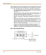
Страница 272: ...spect ratio free of distortion Align the bars horizontally side to side and vertically top to bottom if possible to keep space available on the bar code label Keep a few millimeters 2 4 of empty dead...

Страница 273: ...mulus A7 A9 Positive Control Wells Ctrl These cells either 1 receive a stimulus known to elicit a predetermined response or 2 demonstrate the maximal activity from an agonist In the following experime...

Страница 274: ...having a certain value based on the amount of light crossing over from each of it s neighbors The percentage of crosstalk from wells directly next to B the well of interest is assumed to be different...

Страница 275: ...g Spatial Uniformity Correction The correction factor is derived by calculating the mean fluorescence counts of all wells at Sample 1 see below Sample Time Well A1 Ctrl A2 Ctrl A3 Ctrl A4 Exp A5 Exp A...

Страница 276: ...wells non dye loaded cells or a panel of cells containing different dyes and or dye concentrations the well specific fluorescence counts will be skewed by the correction factor However the EC50 of th...

Страница 277: ...Mean Correction Factor 1 0 8960 8925 8930 8938 1 00 2 5 9194 9030 8836 9017 0 99 3 10 9408 8925 8648 8994 0 99 4 20 9632 8820 8648 9033 0 99 5 25 9632 9240 8648 9173 0 97 6 30 9856 8925 8930 9237 0 9...

Страница 278: ...ts between Sample 1 and all of the samples is calculated 3 The greatest difference is determined 4 100 is divided by the greatest difference in fluorescence counts determined above to give the positiv...

Страница 279: ...Subtract Bias In our example the percent positive fluorescence at Sample 1 is around 20 for all wells Subtracting the background at Sample 1 would make the data easier to interpret Sample 1 or any sa...

Страница 280: ...e mean fluorescence counts in each well between the baseline start and end samples see below All samples taken from a particular well are divided by their well specific mean baseline correction factor...

Страница 281: ...0 6 Sample Time Well A1 Ctrl A2 Ctrl A3 Ctrl A4 Exp A5 Exp A6 Exp A7 Ctrl A8 Ctrl A9 Ctrl 1 0 0 98 1 00 1 01 0 98 1 01 0 98 1 03 0 99 96 2 5 1 00 1 01 1 00 1 00 0 99 1 00 0 98 1 01 1 00 3 10 1 02 1 00...

Страница 282: ...Data Processing Algorithms 282 0112 0109 H...

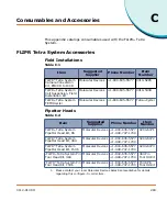
Страница 283: ...ra Cycler Table C 2 Item Suggested Supplier Phone Number Item Number FLIPR Tetra System Pipettor Head Kit 96 Molecular Devices 1 800 635 5577 1 408 747 1700 0200 6071 FLIPR Tetra System Pipettor Head...

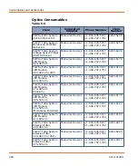
Страница 284: ...5 FLIPR Tetra System LED Module 420 455 nm Molecular Devices 1 800 635 5577 1 408 747 1700 0200 6148 FLIPR Tetra System LED Module 470 495 nm Calcium Molecular Devices 1 800 635 5577 1 408 747 1700 02...

Страница 285: ...200 6214 FLIPR Tetra System Custom Filter Set 3 Molecular Devices 1 800 635 5577 1 408 747 1700 0200 6221 Table C 4 Item Suggested Supplier Phone Number Item Number FLIPR Tetra System pipette tips bla...

Страница 286: ...nfigure to order item Table C 5 Item Suggested Supplier Phone Number Item Number FLIPR Tetra System Cell Suspension Reservoir Molecular Devices 1 800 635 5577 1 408 747 1700 0200 6222 FLIPR Tetra Syst...

Страница 287: ...766 7000 165305 Black clear tissue culture treated sterile poly D lysine coated Becton Dickinson 1 800 343 2035 356640 Corning Costar 1 800 492 1110 3667 Black clear tissue culture treated sterile co...

Страница 288: ...1 polypropylene Nalge Nunc 1 800 766 7000 249944 U bottomed plate 96 well Becton Dickinson 1 800 343 2035 351190 polypropylene Corning Costar 1 800 492 1110 3365 polypropylene Nalge Nunc 1 800 766 700...

Страница 289: ...thick glass Nalge Nunc 1 800 766 7000 142761 Black clear bottom tissue culture treated sterile poly D lysine coated Becton Dickinson 1 800 343 2035 356663 Corning Costar 1 800 492 1110 3664 Black clea...

Страница 290: ...1 800 492 1110 3657 polypropylene Greiner distributed by E K 1 408 378 2013 781280 polypropylene Nalge Nunc 1 800 766 7000 264573 polypropylene Deep well plate Becton Dickinson 1 800 343 2035 353996 p...

Страница 291: ...hone Number Item Omni tray Nalge Nunc 1 800 786 7000 2428110 polystyrene Table C 14 Item Suggested Supplier Phone Number Item FLIPR Calcium 5 Assay Kit Bulk Kit Explorer Kit Express Kit Molecular Devi...

Страница 292: ...alanced Salt Solution 10X stock Gibco 1 800 828 6686 14065 056 HEPES buffer solution 1X Irvine Scientific 1 800 437 5706 9319 Probenecid crystalline Sigma 1 800 325 3010 P8761 Carbachol receptor media...

Страница 293: ...counter Sterile test tubes 15 mL and 50 mL or smaller tubes for compounds dilutions 1 N NaOH solution to dissolve probenecid Table C 15 Item Suggested Supplier Phone Number Item FLIPR Membrane Potenti...

Страница 294: ...Consumables and Accessories 294 0112 0109 H...

Страница 295: ...val of residue AquaMax Sterilant was developed for the purpose of removing organic and inorganic material and killing microorganisms including endospores in liquid handling instrument fluid paths In a...

Страница 296: ...trate Solution A and 3 parts deionized water 1X Solution A may be stored for 30 days in a capped bottle between 10 and 40 C Preparation of complete Sterilant 1 Within 1 hour of use add 0 2 final v v S...

Страница 297: ...lt the Material Safety Data Sheet for Solutions A and B 3 As supplied Solution A may not be sterile 4 The following information is being provided in compliance with Worker and Community Right To Know...

Страница 298: ...Using AquaMax Sterilant 298 0112 0109 H...

Страница 299: ...decontamination was performed ________________________________________________________ ________________________________________________________ ________________________________________________________...

Страница 300: ...ate 300 0112 0109 H Enclose this sheet with the part or instrument being shipped to another location or returned to the factory Please enclose the sheet in such a manner that it can be easily read whe...

Страница 301: ...iate radio frequency energy and if not installed and used in accordance with the instructions may cause harmful interference to radio communications However there is no guarantee that interference wil...

Страница 302: ...Electromagnetic Compatibility EMC 302 0112 0109 H...

Отзывы: