


Setting Parameters
01/02 AWB8230-1415GB
142
Settings in frequency control mode
Before you use PID mode, you must configure the parameters in
frequency control mode. Observe the following two points:
Acceleration and deceleration ramp
The output frequency calculated with the PID algorithm is not
immediately available at the frequency inverter output, as the
output frequency is affected by the set acceleration and decelera-
tion times. Even if, for example, a large D component is defined,
the output frequency is significantly influenced by the acceleration
and deceleration time, and this causes unstable control behaviour.
To achieve stable behaviour in every PID control range, the acce-
leration and deceleration times should be set as low as possible.
After every acceleration and deceleration ramp parameter change,
parameters PNU A072, A073 and A074 must be readjusted.
Frequency jumps/frequency range
Frequency jumps must be defined to meet the following require-
ment: A change to the feedback actual value signal must not occur
during execution of a frequency jump. If a stable operating point
exists within a frequency jump range, an oscillation between the
end values of this range occurs.
Configuration of setpoint value and actual value
In PID mode, you must first specify how the setpoint is to be
defined and where the actual value is to be supplied. The table
below lists the required settings:
The setpoint value and the actual value cannot be supplied
through the same analog input terminal.
Note that the frequency inverter brakes and stops according to the
set deceleration ramp as soon as a stop signal is issued in PID
operation.
Scaling
Set the scaling to the process-corrected physical unit as required
by your application, for example to flow, pressure or temperature.
For a detailed description,
a
Section “Scaling adjustment“,
Page 141.
Setpoint adjustment through digital inputs
The following points must be observed when defining the setpoint
through the digital inputs (4 bit):
Assignment of the digital inputs
The DV6 frequency inverters have eight programmable digital
inputs. Assign functions FF1 to FF4 to four of the inputs using
PNU C001 to C006 to correspond to inputs 1 to 6 of the inverter.
Adjustment of the setpoint values
First, select the required number of different setpoints (up to 16)
from the table below. Under PNU A021 (corresponds to the first
setpoint value) to A035 (corresponds to the 15th setpoint value),
enter the desired setpoint value. PNU A020 and F001 correspond
to setpoint 0.
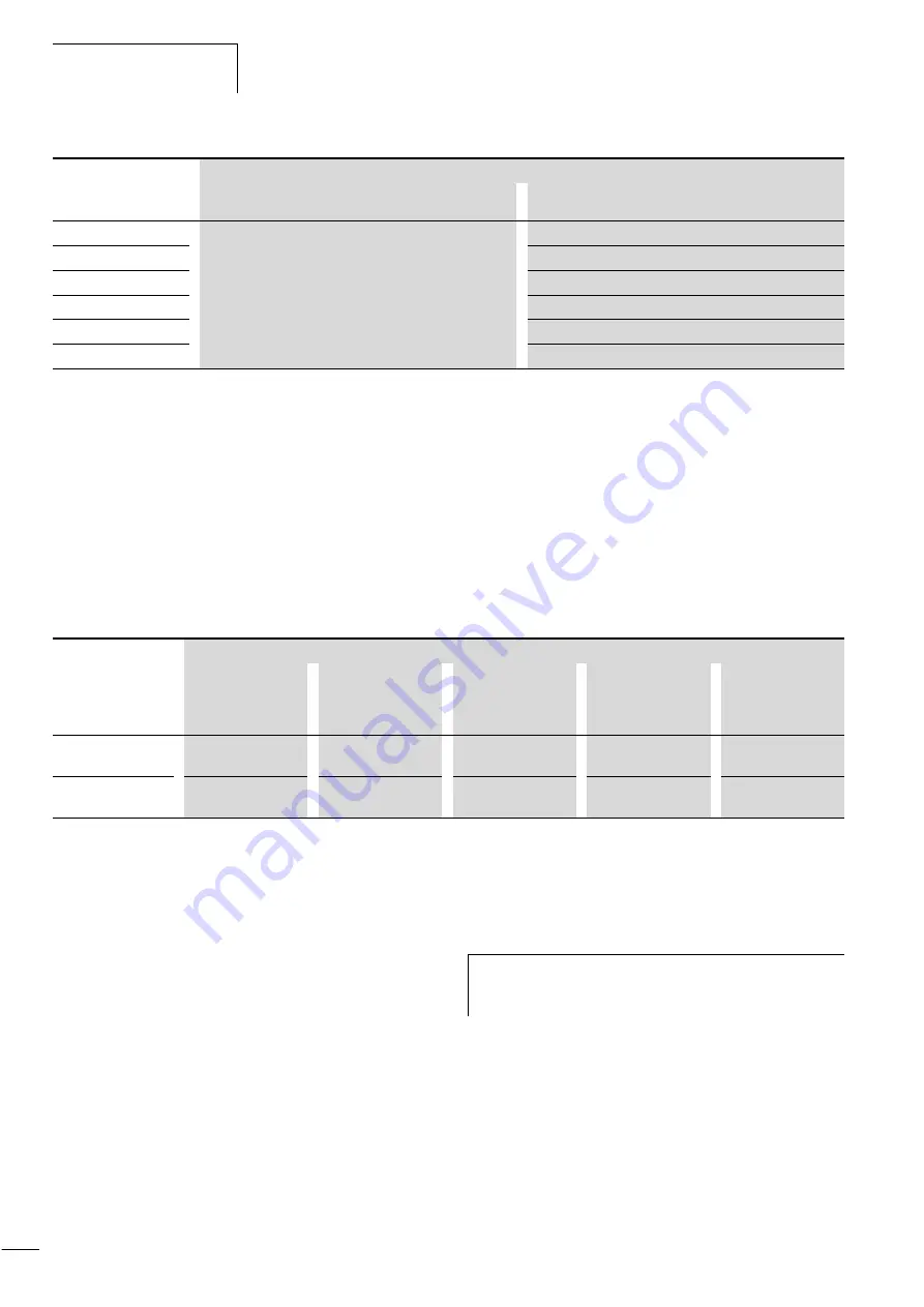
A071
–
PID control active/inactive
A072
P component of the PID control
A073
I component of the PID control
A074
D component of the PID control
A075
Setpoint factor of the PID control
A076
Input actual value signal for PID control
PNU
Meaning of the parameters when used in
Frequency control mode
PID mode
Actual value input
Setpoint definition
Built-in keypad
Digitally through
control terminals
(fixed frequencies)
Integrated potenti-
ometer
Analog voltage at
O-L
Analog current at
OI-L
Analog voltage
(O-L: 0 to 10 V)
PNU A001 = 02
PNU A076 = 01
PNU A001 = 02
PNU A076 = 01
PNU A001 = 00
PNU A076 = 01
–
PNU A001 = 01
PNU A076 = 01
Analog current
(OI–L: 4 to 20 mA)
PNU A001 = 02
PNU A076 = 00
PNU A001 = 02
PNU A076 = 00
PNU A001 = 00
PNU A076 = 00
PNU A001 = 01
PNU A076 = 00
–
h
If the setpoints are to be scaled, note that they must be
entered as process-corrected quantity values in accor-
dance with this scaling.
For Moeller Electric Sales and Support call KMparts.com (866) 595-9616


