Modul-Connect
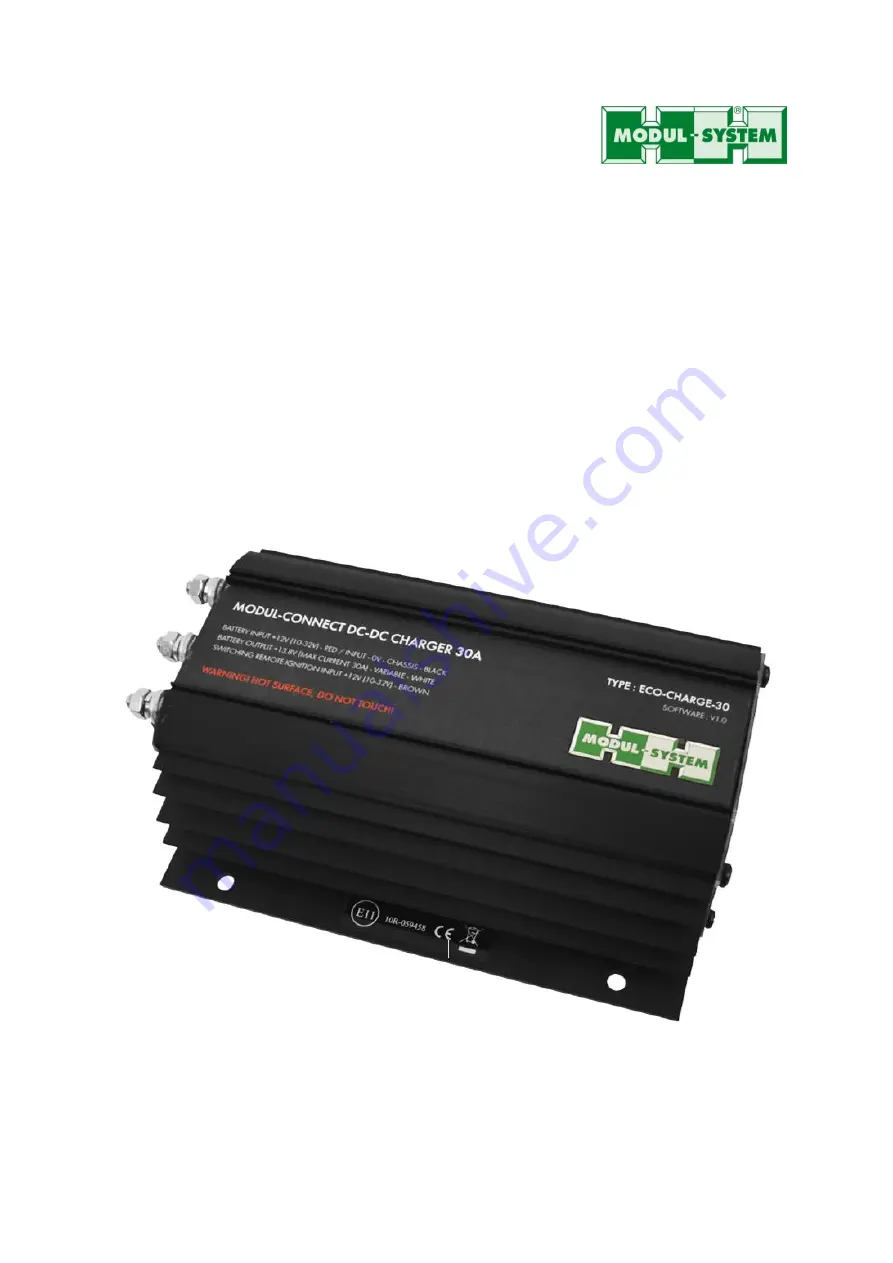
Battery Charger DC-DC 30A
Owner’s Manual
Страница 1: ...Modul Connect Battery Charger DC DC 30A Owner s Manual ...
Страница 2: ...o responsibility for errors or omissions Note as well that specifications and product functionality may change without notice Important Please be sure to read and save the entire manual before using your Modul Connect Battery Charger DC DC 30A Misuse may result in damage to the charger and receiving vehicle and or cause harm or serious injury Product Number 21500 04 Modul Connect Battery Charger D...
Страница 3: ...Important safety information 1 2 Product description 3 3 Installation 3 4 Battery charger DC input connection 6 5 Charger operation 8 6 Troubleshooting 9 6 1 Understanding the error codes 9 7 Technical specification 10 8 Warranty 11 ...
Страница 4: ...rsonal protective equipment including eye protection that protects eyes from all angles and gloves Avoid touching your eyes while installing the battery charger Keep fresh water and soap on hand in the event battery acid comes in contact with eyes If this occurs cleanse right away with soap and water for a minimum of 15 minutes and seek medical attention ALWAYS remove personal metal items such as ...
Страница 5: ...jury to persons and damage to property This system is not intended to supply low voltage power for applications other than battery charging DANGER Shock Hazard Keep away from children The battery charger s internal components are conformal coated to cope with lower temperatures It is advisable to avoid moisture Never expose unit to snow water etc DANGER Explosion hazard DO NOT use the Modul Connec...
Страница 6: ... DC DC 30A Connection pack Owner s manual 3 Installation WARNING Modul System recommends that all wiring be done by a certified technician or electrician to ensure adherence to the applicable electrical safety wiring regulations and installation codes Failure to follow these instructions can damage the unit and could also result in personal injury or loss of life CAUTION Before beginning your inst...
Страница 7: ...d on the charger A 2A mini blade fuse and several connection options for the ignition sensing cable are also supplied Never replace a fuse with one that has different amperage than the original on the DC Input Output and ignition positive cables Cable Use the low resistance cable that is supplied with the charger for all the DC connections between the battery charger and the battery bank The batte...
Страница 8: ...e battery charger has 4 off fixing holes 6 5mm diameter and 4 off fixing slots 6mm x 10mm for ease of mounting It is recommended to use a minimum of 4 off M5 fixings to secure the battery charger Drill the 4 mounting holes place the charger in position and fasten it to the mounting surface IMPORTANT Connection Procedure Power up sequence to ensure normal operations 1 Remove all in line fuses from ...
Страница 9: ...use box of the vehicle to piggy back from an ignition circuit without cutting into any cables on the vehicle The mini blade ignition jumper has two circuit slots on one side and a fuse plug on the other When plugged into one of the vehicle s circuit slots the fuse tap provides space for an additional fuse The mini blade ignition jumper MUST NOT be used to replace the fuse in any primary vehicle sa...
Страница 10: ... box and remove selected fuse 4 Insert fuse jumper into fuse box OPTIONS 2 3 Connect to a vehicle positive ignition supply via the supplied 2A fuse using OEM vehicle manufactures recommendations Further connection information for vehicle makes and models is available from Modul System NOTE When removing the ignition fuse from the fuse box test for the positive terminal out of the fuse box The posi...
Страница 11: ...when it cools down The 3 colour status LED on the battery charger end panel shows the status of the charger In normal operation the LED will either be off ignition key off flashing amber charging or green charged The 3 colour status LED also shows the status of the charger as follows Status LED colour Status LED output Mode Note Off Off Off Ignition off The charger is switched off Red Flashing Fau...
Страница 12: ...er LED flashes AMBER but the battery voltage is not increasing wait 10 minutes and re check your readings 6 1 Understanding the error codes Status LED colour Short flashes Long flashes Fault Red 3 0 Force idle check connection and fuses to chassis battery and auxiliary battery Red 3 1 Starter battery voltage below 9 volts 9V Red 3 2 Starter battery voltage over 36 volts 36V Red 3 3 Starter battery...
Страница 13: ...ensing 90 non condensing IP Rating IP60 in any mounting position IP65 mounted vertically with the cable connections at the bottom of the charger SAFETY AND ENVIRONMENTAL CE EMC LVD EN61000 4 5 2014 EN61204 3 2000 EN61000 4 6 2014 EN61000 4 2 2009 CISPR16 2 3 2006 EN61000 4 3 2009 A1 2008 A2 2010 EN50581 2012 DIMENSIONS AND WEIGHTS Shipping Weight 3 2 Kg Dc Dc Charger Weight 1 Kg Dc Dc Charger Loom...
Страница 14: ... to a customer service representative if products are deemed non working or malfunctioning the product may be returned to Modul System within 30 days of original purchase Any defective unit that is returned to manufacturer within 30 days of the date of purchase will be replaced free of charge If such a unit is returned more than 30 days but less than two years from the purchase date manufacturer w...