background image


AC 230V 50Hz 1465W (5000BTUs) 


BGM20201123.V2


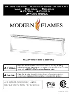
SPECTRUM SLIMLINE WALL MOUNT/RECESSED ELECTRIC FIREPLACE


Model# : 

     SPS-50B-AU 

SPS-60B-AU 


SPS-74B-AU              SPS-100B-AU


OWNER’S MANUAL


Read and understand 

this entire owner’s manual, including 

all safety 

information

, before 

plugging in 

or 

using 

this product. Failure to do so could 

result in 

fire, electric shock, or serious personal injury. 

Keep this owner’s manual 

for future reference. If you sell or give this 

product away, 

make sure this manual accompanies this product

AFFIX SERIAL NUMBER LABEL 
HERE FOR FUTURE REFERENCE


WARNING 

CAUTION 

Содержание SPS-100B-AU

Страница 1: ...and this entire owner s manual including all safety information before plugging in or using this product Failure to do so could result in fire electric shock or serious personal injury Keep this owner s manual for future reference If you sell or give this product away make sure this manual accompanies this product AFFIX SERIAL NUMBER LABEL HERE FOR FUTURE REFERENCE WARNING CAUTION ...

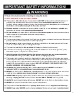
Страница 2: ... in areas where gasoline paint flammable vapors or liquids are used or stored l Use this heater only as described in this manual Any other use not recommended by the manufacturer may cause fire electric shock or injury to persons l This heater may include an audible or visual alarm to warn that parts of the heater are getting excessively hot If the alarm sounds or illuminates immediately turn the ...

Страница 3: ... draw more current than small appliances Overheating may occur even if it has not occurred with the use of other appliances iii During use check frequently to see if the plug outlet or face plate is HOT iv If the outlet or face plate is HOT discontinue use immediately and have a qualified electrician inspect and or replace the faulty outlets l SAVE THESE INSTRUCTIONS Preparation Remove all parts a...

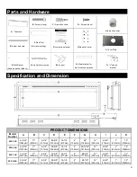
Страница 4: ...DIMENSIONS Model Number A B C D E F G H I J K SPS 50B 49 3 4 1264mm 17 430mm 4 3 4 121mm 48 5 8 1235mm 16 1 8 410mm 4 102mm 46 1168mm 12 305mm 4 5 8 118mm 1 25 4mm 72 1829mm SPS 60B 59 3 4 1518mm 17 430mm 4 3 4 121mm 58 5 8 1489mm 16 1 8 410mm 4 102mm 55 13 16 1418mm 12 305mm 4 5 8 118mm 1 25 4mm 72 1829mm SPS 74B 73 3 4 1873mm 17 430mm 4 3 4 121mm 72 5 8 1845mm 16 1 8 410mm 4 102mm 69 3 4 1772mm ...

Страница 5: ... furniture and high traffic areas NOTE Follow all National and local electrical codes MINIMUM CLEARANCE TO COMBUSTIBLES Measurements are taken from the glass front Bottom 0 Sides 0 Back 0 Top 11 8 300mm to mantel Top 11 8 300mm to ceiling MINIMUM MANTEL CLEARANCES WHEN USING PAINT OR LACQUER TO FINISH THE MANTEL THE PAINT OR LACQUER MUST BE HEAT RESISTANT TO PREVENT DISCOLOURATION WARNING ...

Страница 6: ...m falling remove the two screws 1 per side from the side of the appliance Fig 1 1 Set the screws aside B Carefully lift the front glass up and away from the appliance Fig 1 2 Place it face down on a soft non abrasive surface C Reverse these steps to install the front glass Fig 1 1 Fig 1 2 ...

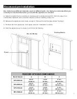
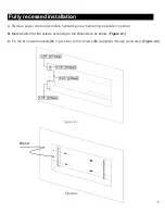
Страница 7: ... furniture bedding paper etc B Measure the appliance and create a rough in frame with electrical see below framing C Remove the front glass see front glass removal installation section D Hold the appliance up to ensure it will fit into the framing Power FINISHED OPENING DIMENSIONS Model Number A B C SPS 50B AU 48 7 8 1242mm 16 1 4 413mm 4 min 102mm min SPS 60B AU 58 7 8 1496mm 16 1 4 413mm 4 min 1...

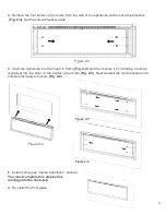
Страница 8: ...nd complete hardwiring see hardwiring installation section B Mark location for the screws according to the dimensions as below Figure 2 1 C Fix the two metal brackets N 1per side with 4 screws B supplied through wood stud Figure2 2 Wood Stud Figure 2 2 ...

Страница 9: ...o the rough in frame Fig 2 4 and then secure it by installing 4 screws supplied into the slots on the insides 2 per side Fig 2 5 Next reinstall the two brackets and 4 screws previously removed Fig 2 6 Figure 2 4 F Install media see media installation section You must complete this step before movingonto the next step G Re install the front glass Figure 2 5 Figure 2 6 ...

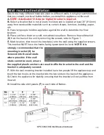
Страница 10: ...nt the bracket s onto the wall using the supplied screws This bracket MUST have the hooks facing upward and be level NOTE It is strongly recommended that the mounting bracket K be Screwed into the wall studs where possible If the wall studs cannot be used ensure the supplied plastic anchors are used to affix the bracket to the wall and the bracket is adequately secured F With the wall mounting bra...

Страница 11: ... B Using the screw previously removed attach the L bracket O supplied to the bottom of the fireplace box Fig 3 2 C Install the plastic anchor C into the dry wall then install the screw B supplied into the hole of the L bracket into the wall anchor to secure the fireplace from coming off the hooks Fig 3 3 11 Size A B C D 100 5 3 8 136 5mm 4 1 4 108mm 9 5 8 244 5mm 3 1 4 82 5mm F D Fig 3 1 Fig 3 3 ...

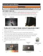
Страница 12: ...rews as shown above SEE FIG 1 B Remove the wire nuts from the power cord The power cord may be discarded SEE FIG 2 C Take the new cover plate supplied in the hardware bag and punch out the 7 8 22 2mm hole and install cable connector through into the junction box Snap the cable connection clamp onto the supply wires D Using the wire nuts connect the ground green wires G the common white wires N tog...

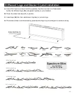
Страница 13: ... E in position C Install logs M first then add Glacier Crystals L around logs D Photo below shows recommended log placement but logs may be arranged to customer s liking Ember Bed Strip E 50 Set Contains 8 Logs 60 Set Contains 9 Logs Log sets may vary and are subject to change 74 Set Contains 12 Logs 100 Set Contains 16 Logs 10 12 Log 1 Log 2 Log 3 Log 5 Log 4 Log 7 Log 10 Log11 Log 12 Spectrum Sl...

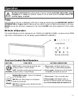
Страница 14: ...anel functions and remote control Turns on flame OFF Disables control panel functions and remote control Turns off flame 1 Press once Indicator light turns on Power turns on All functionsenabled 2 Press again Flame turns off Unit goes to standby All functions turn off MEDIA MEDIA BED button Turns on mediabed and changes color NOTE color effect stays on until power button is turned off NOTE this fi...

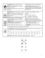
Страница 15: ...the heater turns on and after the heater turns off Turns the heater and blower on off Settings H0 Heater and blower off H1 Low Heater on with 750W H2 High Heater on with 1500W NOTE Press and hold the heater button for 5 seconds to lock unlock the heater and thermostat TIMER TIMER button Controls timer settings to turn off fireplace at selected time Settings range from 30min to 8 hours 1 Press once...

Страница 16: ...or is reached In total ten colors for flame and one fade mode From 01 02 03 04 05 06 07 08 09 10 11 FLAME BRIGHT NESS FLAME brightness button Makes flame dimmer and brighter NOTE Flame stays on until power button is turned off 1 Press once Flame brightness enabled 2 Press again until desired setting is reached From F5 F4 F3 F2 F1 HEATER HEATER button Turns heater on and off NOTE The heater only wo...

Страница 17: ...il desired setting is reached In total 5 levels From L5 L4 L3 L2 L1 Temperature Limiting Control This heater is equipped with a Temperature Limiting Control Should the heater reach an unsafe temperature the heater will automatically turn OFF To reset 1 Unplug the power cord from the outlet Wait 5 minutes 2 Inspect the fireplace to make sure no vents are blocked or clogged with dust or lint If they...

Страница 18: ...nts are integrated in the fireplace and are not serviceable by theconsumer Storage Store heater in a clean dry place when not in use NEVER dispose of batteries in fire Failure to observe this precaution may result in an explosion Dispose of batteries at your local hazardous material processing center ALWAYS turn the heater OFF and unplug the power cord from the outlet before cleaning performing mai...

Страница 19: ...19 Spare Parts List ...

Страница 20: ...umber at AUSTRALIA NEW ZEALAND 07 5630 6837 Monday Friday 9 00AM 4 00PM AEST Or email us at info modernflames com EUROPE 46 762 09 58 09 Monday Friday 9 00AM 4 00PM CEST Or email us at europe modernflames com NORTH AMERICA 1 877 246 9353 Monday Friday 8 00AM 5 00PM AZ MST Or email us at customerservice modernflames com OUR STAFF IS READY TO PROVIDE ASSISTANCE ...

Отзывы: