5
5.4 Operation Mode Change Function
5
- 58
1
OV
ER
VIE
W
2
SYS
TEM
CONFIGURA
TI
ON
3
TR
AC
KI
N
G
C
ABL
E
4
P
R
OCE
DURE
FO
R
S
TAR
TING
UP
A
RE
DUN
DAN
T
S
Y
S
T
E
M
5
RE
DUNDA
NT S
Y
S
T
E
M
FUNCTIONS
6
RE
DUN
DAN
T
S
Y
S
T
E
M
NE
TW
O
R
K
S
7
PR
OG
R
A
MM
IN
G
CA
UTIO
N
S
8
TR
O
U
BLE
S
HOOTING
5.4 Operation Mode Change Function
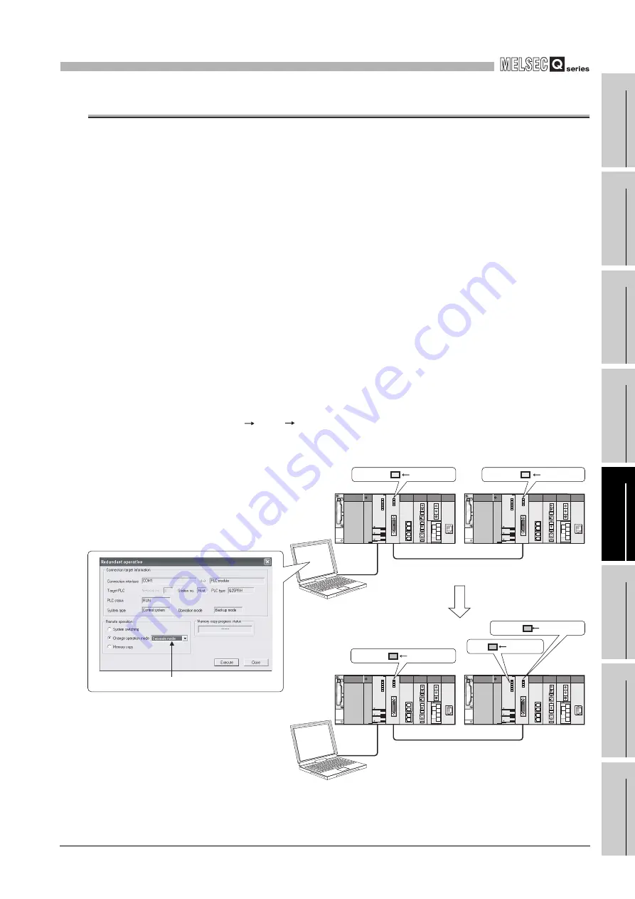
2 types of redundant system operation mode change are available.
• Change from the backup mode to separate mode
• Change from the separate mode to backup mode
Refer to Section 5.1.3 for details on the backup mode and separate mode.
(1) Operation Mode Change Procedure
The operation mode change is performed in the control system CPU module by the
redundant operation of GX Developer.
(a) Changing from the Backup Mode to Separate Mode
1) Connect GX Developer to the control system CPU module.
2) Select "Online" - "Redundant operation" from the menu bar of GX Developer to
open the "Redundant operation" screen.
3) Open the GX Developer online Redundancy Procedure window.
Check the "Change operation mode" at the redundant operation area, and
then select "Separate mode" from the list.
4) Click the Execute button.
5) Set the RUN/STOP switch of the standby system CPU module to
RUN STOP RUN, or use GX Developer to change from remote STOP to
remote RUN. With this setting, the CPU module starts running and executes.
*1
* 1: When changing from the backup mode to the separate mode, the RUN LED of the standby
system CPU module will flash and will be in a stop status.
Diagram 5.33 Operation when Changing from Backup Mode to Separate Mode
Change to separate mode
Control system
[Run in backup mode]
Standby system
Control system
[Run in separate mode]
Standby
system
separate mode
change operation
GX Developer
GX Developer
Select "Separate mode"
Tracking cable
Tracking cable
BACKUP ON (green)
BACKUP ON (green)
BACKUP ON (amber)
BACKUP
ON (amber)
RUN flashing
*1


