8 - 4
MELSEC-Q/QnA
8. INCOMPLETE DERIVATIVE PID CONTROL INSTRUCTIONS
AND PROGRAM EXAMPLES
(6) For
S
, designate the first number of the device numbers that are designated in
the I/O data area. If file registers (R) are designated for the I/O data area, do not
set memory protect ON for the file registers (R).
If memory protect is set ON, correct PID operation will be precluded, although no
error will occur.
See Section 5.2 for details on the I/O data area.
(7) Execute the S.PIDCONT instruction in every scan even while the manual
manipulated value (MV
MAN
) is being output in the manual control mode.
The bumpless switching cannot be executed if the S.PIDCONT instruction has
not been executed.
See Section 4.3.1 for details on the bumpless switching.
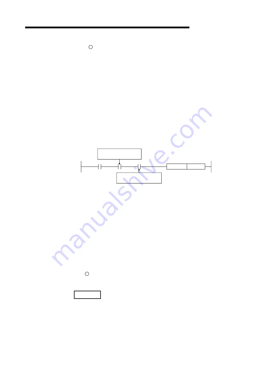
(8) Use the READY signal to establish an interlock with respect to the individual
modules, so that the S.PIDCONT instruction is executed only when both the A/D
converter module for reading the PV (process value) and the D/A converter
module for outputting the MV (manipulated value) are normal.*
S.PIDCONT
D100
Control command
READY signal for the
A/D converter module
READY signal for the
D/A converter module
If the S.PIDCONT instruction is executed while either or both of the modules are
faulty, PID operation cannot be executed correctly because the PV (process
value) cannot be read correctly and/or the MV (manipulated value) cannot be
output correctly.
[OPERATION ERRORS]
(1) An operation error will occur, the error flag (SM0) will be turned ON, and an error
code will be stored in SD0, in the following cases.
•
When the S.PIDINIT instruction is executed before executing the S.PIDCONT
instruction. (Error
code
:
4103)
•
When the value set as the PID control data is outside the allowable range.
(Error code
:
4100)
•
When the device range allocated to the PID control data area, designated with
S
, exceeds the last device number of the corresponding device.
(Error
code
:
4101)
REMARK
*: For details on the READY signals of the A/D converter module and D/A converter
module, refer to the manual for the relevant module.
Содержание Q Mode
Страница 1: ......
Страница 2: ......
Страница 14: ...A 12 MEMO ...
Страница 18: ...1 4 MELSEC Q QnA 1 GENERAL DESCRIPTION MEMO ...
Страница 48: ...4 14 MELSEC Q QnA 4 FUNCTIONS OF PID CONTROL MEMO ...
Страница 51: ...5 3 MELSEC Q QnA 5 PID CONTROL PROCEDURE MEMO ...
Страница 65: ...5 17 MELSEC Q QnA 5 PID CONTROL PROCEDURE MEMO ...
Страница 72: ...5 24 MELSEC Q QnA 5 PID CONTROL PROCEDURE MEMO ...
Страница 74: ...6 2 MELSEC Q QnA 6 PID CONTROL INSTRUCTIONS MEMO ...
Страница 120: ...9 28 MELSEC Q QnA 9 COMPLETE DERIVATIVE PID CONTROL INSTRUCTIONS AND PROGRAM EXAMPLES MEMO ...
Страница 125: ......
Страница 126: ......


