


18. GOT MULTI-DROP CONNECTION
18.7 Precautions
18 - 23
18
GOT MU
L
T
I-DROP CONN
ECTION
18.7 Precautions
Connecting GOT2000 in multi-drop
connection
(1) Standard monitor OS installation, Writing
Communication driver
When connecting GOT2000 in multi-drop connection,
the writing of the standard monitor OS and
communication driver to the GOT from GT Designer3
(GOT1000) (Version 1.12N or later), as well as the
writing of the standard monitor OS and communication
driver to the serial multi-drop connection unit are
required
The standard monitor OS or communication driver
cannot be installed from GT Designer3 (GOT2000).
(2) Device specification
Network No. and station No. are not supported.
Station number setting on GOT
Set each station number so that no station number
overlaps.When the station No. is duplicated, the GOT
whose station No. is duplicated cannot be monitored
normally.
The station number can be set without regard to the
cable connection order.There is no problem even if
station numbers are not consecutive.
Extended/Option function of GOT
The extended/option functions of GOT shown below
are not available.
System monitor, Device monitor, Ladder monitor, A list
editor, FX list editor, Intelligent unit monitor, Network
monitor, Q motion monitor, Servo amplifier monitor,
CNC monitor, Backup/restore, CNC data I/O, SFC
monitor, Ladder editor, Log viewer, MELSEC-L
troubleshoot, Motion SFC, motion program (SV43)
editor, Motion program (SV43) I/O
System alarm
The alarms of the serial multi-drop connection unit are
displayed on the system alarm.The alarms of the
connected PLC are not displayed.
Activating the serial multi-drop connection
unit
The master module detects a slave GOT, which is
connected, at the startup.It may take time to detect
again the slave station which is not detected at this
point.Activate the master module in the condition that a
communication can be made after the startup of the
slave GOT.
Using the multi-drop connection in the multi-
channel configuration
If a communication timeout error occurs when using the
multi-drop connection in the multi-channel
configuration, set the send delay time to the serial
multi-drop connection unit side.
■
Device update cycle
• When the number of connected slave GOTs and the
device points of each GOT increase, the device
update cycle on the screen may get slower. In such a
case, it is recommended to reduce the device points
of each GOT. (Please consider 250 points as a guide
of 1 GOT, and 750 points as a guide of the total
points.) In addition, when a timeout error occurs,
make the timeout time longer in the communication
settings of the slave GOT.
• When the device number is set randomly, the device
update cycle becomes slower compared to the case
that the device number is set consecutively.Therefore,
it is recommended to set the device number
consecutively.
• Depending on the device points or combination, it
may take time to switch the screen.At this time, the
device update cycle of other slave station is also
affected.
FA transparent function
FA transparent function is available for each GOT in the
GOT multi-drop connection system.
(1) Standard monitor OS installation, Writing
Communication driver
When using FA transparent function in GOT multi-drop
connection, the writing of the standard monitor OS and
communication driver to the GOT from GT Designer3
(GOT1000) (Version 1.18U or later), as well as the
writing of the standard monitor OS and communication
driver to the serial multi-drop connection unit are
required.
(2) Number of personal computers
Only one personal computer can be connected to the
multi-drop connection system.
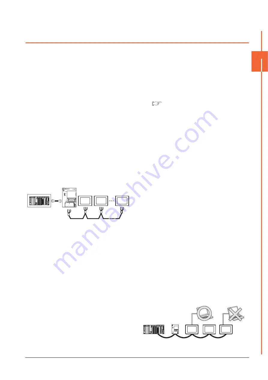
Station
No.3
Station
No.0
Station
No.15
The example of a Station No. setting
Only one personal computer
Содержание GOT2000 Series
Страница 2: ......
Страница 62: ...1 38 1 PREPARATORY PROCEDURES FOR MONITORING 1 6 Checking for Normal Monitoring ...
Страница 64: ......
Страница 80: ...2 16 2 DEVICE RANGE THAT CAN BE SET 2 6 MELSEC WS ...
Страница 246: ...7 26 7 COMPUTER LINK CONNECTION 7 6 Precautions ...
Страница 252: ...8 6 8 BUS CONNECTION 8 1 Connectable Model List ...
Страница 256: ...8 10 8 BUS CONNECTION 8 2 System Configuration ...
Страница 288: ...8 42 8 BUS CONNECTION 8 4 Precautions ...
Страница 324: ...9 36 9 MELSECNET H CONNECTION PLC TO PLC NETWORK MELSECNET 10 CONNECTION PLC TO PLC NETWORK ...
Страница 416: ......
Страница 510: ...15 46 15 SERVO AMPLIFIER CONNECTION 15 7 Precautions ...
Страница 518: ...16 8 16 ROBOT CONTROLLER CONNECTION 16 6 Precautions ...
Страница 540: ...17 22 17 CNC CONNECTION 17 7 Precautions ...
Страница 541: ...MULTIPLE GOT CONNECTIONS 18 GOT MULTI DROP CONNECTION 18 1 ...
Страница 542: ......
Страница 567: ...MULTI CHANNEL FUNCTION 19 MULTI CHANNEL FUNCTION 19 1 ...
Страница 568: ......
Страница 592: ...19 24 19 MULTI CHANNEL FUNCTION 19 3 GOT Side Settings Example Setting example for Ethernet connection 4 channels ...
Страница 599: ...FA TRANSPARENT FUNCTION 20 FA TRANSPARENT FUNCTION 20 1 ...
Страница 600: ......
Страница 668: ...20 68 20 FA TRANSPARENT FUNCTION 20 7 Precautions ...
Страница 670: ...REVISIONS 2 ...
Страница 673: ......


