


7 - 8
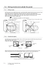
7.2 Wiring inside and outside the panel
7.2.4 Wiring the FG wire of the BUS cable
7.2.4
Wiring the FG wire of the BUS cable
1
To connect the QCPU, motion controller CPU (Q series) and GOT
The cable for connection to the QCPU, motion controller CPU (Q series) does not have a FG wire that
needs to be grounded.
2
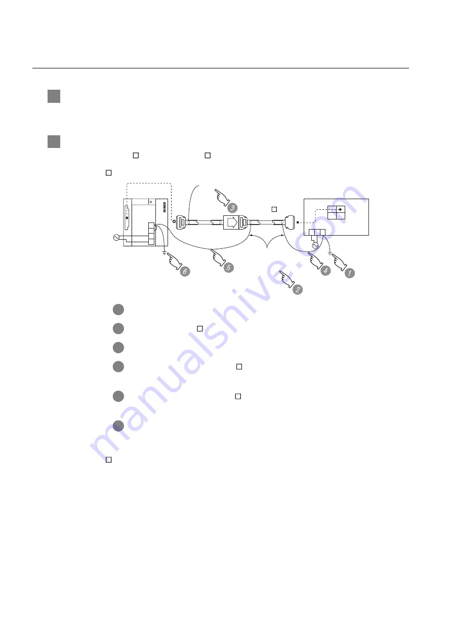
To connect QnACPU, ACPU, motion controller CPU (A series) and GOT
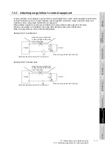
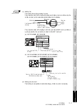
When using GT15-C FXSS-1 or GT15-C BS, ground the FC wires as shown in the figure below.
(1) GT15-C EXSS-1
(2) GT15-C BS
For both GOTs, provide the same grounding as described in the section (1) above to both GOTs.
1
Ground the FG terminal of the power supply terminal block on the GOT.
2
FG wires on GT15-C BS must be 28 cm or less.
3
Leave the FG ground wire on GT15-EXCNB unconnected.
4
Connect the FG wire on GT15-C BS on the GOT side to the FG terminal of
the power supply terminal block on the GOT.
5
Connect the FG wire on GT15-C BS on the PLC side to the FG terminal of the
power supply terminal block on the PLC.
6
Connect the LG and FG terminals on the terminal block, and provide a single
grounding point for them.
FG
LG
N
L
Leave unconnected
(GT15-EXCNB)
GOT
OUT
IN
FG
N
L
PLC
(GT15-C BS)
2SQ wire to the FG
terminals
to be 28 cm or less
Содержание GOT1000 GT11
Страница 1: ......
Страница 2: ......
Страница 251: ...Index 2 U Utility function list 9 2 W Wiring 7 1...
Страница 252: ...Index 3 MEMO...
Страница 255: ......
Страница 256: ......