


18 - 7
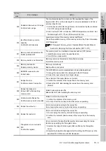
18.3 Troubleshooting in Bus Connection
18.3.1 Locating error positions
18.3 Troubleshooting in Bus Connection
When connect GOT and PLC CPU with bus connection, and the cause is not clear in "18.2 List of Error
Message/System Alarm", execute the following troubleshooting.
Refer to the following for details concerning the bus connection.
GOT1000 Series Connection Manual
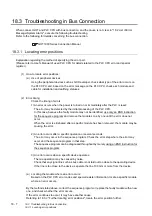
18.3.1 Locating error positions
Explanation regarding the method of specifying the error part.
(Please refer to User's Manual of used PLC CPU for details related to the PLC CPU error and special
register.)
(1) How to locate error positions:
(a) Use of peripheral devices
Using the peripheral devices such as GX Developer, check what type of the error occurs on
the PLC CPU and, based on the error message on the PLC CPU, check each module and
cable for installation and earthing statuses.
(2) Error timing
Check the timing of errors.
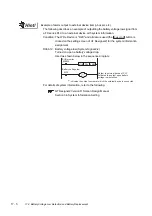
1)An error occurs when the power is turned on or immediately after the PLC is reset:
The error may be detected by the initial processing of the PLC CPU.
In this case, because the faulty module may not be identified, use only an END instruction
for the sequence program and remove the modules one by one until the error does not
occur.
When the error is eliminated after a specific module has been removed, the module may be
causing the error.
2) An error occurs after a specific operation or several seconds:
The error may occur in the sequence program. Check the error step where the error may
occur and the sequence program in that step.
The sequence program can be diagnosed throughout by merely using an END instruction for
the sequence program.
3) An error occurs when a specific device operates:
The mis-operation may be caused by noise.
Check that any signal line such as bus cable is not laid out too close to the operating device.
If the line is too close to the device, separate the line 100 mm or more from the device.
(a) Locating the module where an error occurs:
Based on the PLC CPU error codes and special resister information, locate a specific module
where an error occurs.
By the method stated above, correct the sequence program or replace the faulty module with a new
one, and check whether the error occurs.
If the error continues to occur, it may have another cause.
Referring to 18.3.2 "Further locating error positions", locate the error position further.
Содержание GOT1000 GT11
Страница 1: ......
Страница 2: ......
Страница 251: ...Index 2 U Utility function list 9 2 W Wiring 7 1...
Страница 252: ...Index 3 MEMO...
Страница 255: ......
Страница 256: ......