Appendix - 16
MELSEC-A
APPENDICES
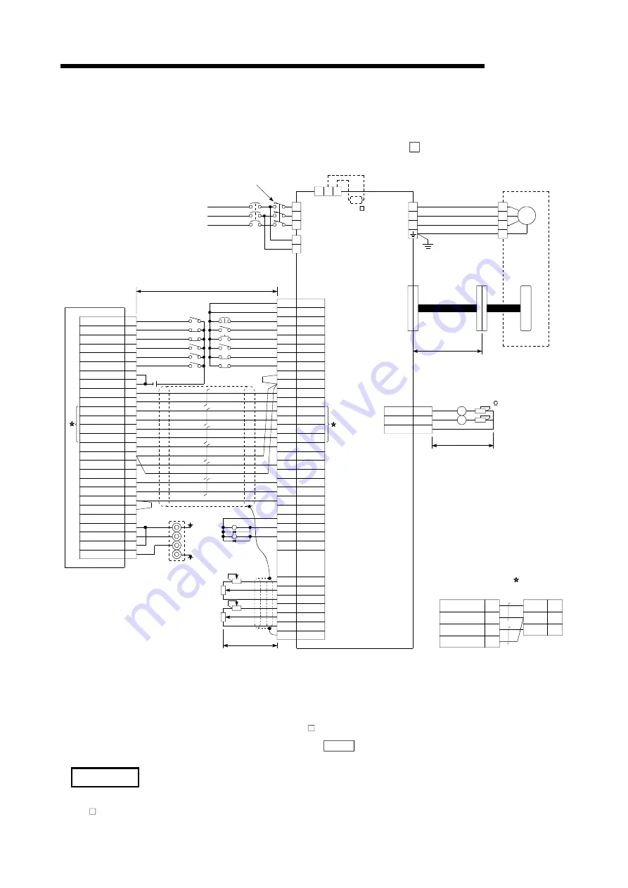
Appendix 4 Connection examples with servo amplifiers manufactured by MITSUBISHI
Electric Corporation
Appendix 4.1 Connection example of A1SD75/AD75 and MR-H A
(Differential driver (Open collector)) *
6
SG
DOC
FLS
RLS
STOP
CHG
STRT
COM
CLEAR
CLEAR COM
PULSE F-
PULSE R+
PULSE R-
READY
PG0(5V)
PG0 COM
PULSER A+
PULSER A-
PULSER B+
PULSER B-
SG
EMG
46
SON
12
RES
15
TL
13
LSP
38
LSN
39
VIN
20
VDD
22
SG
17
PP
10
PPR
11
NPR
36
LZ
8
LZR
9
LG
3
ZSP
23
VDD
21
N15R
26
TLAN
29
LG
30
SD
50
16
Within 10m (within 2m)
CN1
3-phase 200VAC
Power supply
Configure a sequence to turn OFF the MC
at alarms and emergency stops.
R
MC
NF
CN2
Servomotor
D
e
te
ct
or
A1SD75/AD75
PULSE F+
COM
INPS
COM
Upper limit
Near-point dog
Stop
Reset
Speed/position changeover
Start
Torque limit
Forward run stroke end
*3
Servo ON
*3
CR
NP
37
35
Within 2m
R1
S1
S
T
V
W
U
V
W
U
E
SM
Within 50m
N C P
Regeneration option
LG
External emergency stop
11
12
13
14
15
16
35
36
5
3
21
4
22
25
27
23
7
26
10
28
8
24
9
PULSE COM
PULSE COM 20
19
RD
49
PF
24
ALM
48
P15R
1
TLAP
27
28
Analog torque limit co)
+10V/max.current
5V
A
B
0V
RA1
Fault
Zero speed
detection
RA2
24VDC
5G
+5V
Lower limit
Reverse run stroke end
Analog torque limit commmand(-)
-10V/max.current
Manual pulse
generator MR-HDP01
4
1
MO1
MOG
3
MO2
A
Within 2m
Monitor output
Max.1mA total
Two-way deviation
CN3
A
10k
*
4
*
7
*
8
*
2
*
2
*
5
*
4
PULSE F
1
PULSE COM 19
PULSE R
2
PULSE COM
20
PP0
18
SG
47
NP0
19
A1SD75/AD75
CN1
When connected with an open collector,
wire the sections indicated by as shown below.
MR-H A
40
*1 Assignment of the pin numbers of the connector of the A1SD75/AD75 is the same for axes 1 to 3.
*2 The upper limit (FLS) and lower limit (RLS) of the A1SD75/AD75 are used for the zero point return retry function. Set these inside
the limit switches for the servo.
*3 Limit switch for servo (stopping).
*4 For details of connection, refer to the specification manual of the servo amplifier MR-H.
*5 The distance between the controller and amplifier is indicated. The distance must be within 2m with the open collector.
*6 Use “Logic selection for pulse output to the drive unit” specified in detailed parameter 1 to match the logic (positive or negative
logic) between the A1SD75/AD75 and the servo amplifier. The initial setting of A1SD75/AD75 is a positive logic.
*7 Use the output module to issue a clear signal to the MR-H A in a simple absolute position detection system.
(Do not use the deviation counter clear output of the AD75.)
*8 There is no need to wire the in-position signal. (It is output as “
Md.39
External input/output signal” but it is not used for internal
processes of the AD75.)
REMARK
The AD75C20SH cable (for differential driver) can be used for the connection between the A1SD75/AD75 and MR-
H A. (Refer to section 2.2 “List of configuration devices.”)
Artisan Technology Group - Quality Instrumentation ... Guaranteed | (888) 88-SOURCE | www.artisantg.com
Содержание A1SD75P1-S3
Страница 2: ...Artisan Technology Group Quality Instrumentation Guaranteed 888 88 SOURCE www artisantg com...
Страница 3: ...Artisan Technology Group Quality Instrumentation Guaranteed 888 88 SOURCE www artisantg com...
Страница 16: ...A 13 MEMO Artisan Technology Group Quality Instrumentation Guaranteed 888 88 SOURCE www artisantg com...
Страница 23: ...A 20 MEMO Artisan Technology Group Quality Instrumentation Guaranteed 888 88 SOURCE www artisantg com...
Страница 25: ...MEMO Artisan Technology Group Quality Instrumentation Guaranteed 888 88 SOURCE www artisantg com...
Страница 275: ...MEMO Artisan Technology Group Quality Instrumentation Guaranteed 888 88 SOURCE www artisantg com...
Страница 617: ...Index 12 MEMO Artisan Technology Group Quality Instrumentation Guaranteed 888 88 SOURCE www artisantg com...
Страница 620: ...Artisan Technology Group Quality Instrumentation Guaranteed 888 88 SOURCE www artisantg com...
Страница 621: ...Artisan Technology Group Quality Instrumentation Guaranteed 888 88 SOURCE www artisantg com...


