background image

– 3 –

3

Installation

1. Parts prepared at site

Please prepare the following parts before installation of the unit.

Preparation parts

Unit fixing screw

Power cable/

Protective earth cable

Main power switch
(Circuit breaker)

Transmission cable

DC power cable

Specification

M4 screw 

×

 4pcs

Please prepare the power cable in compliance with your applicable technical standard with consid-
eration to the power requirement of the unit.

* Recommend type;

φ

1.5mm ~ 

φ

2.0mm (Example: H03VV-F, H03VVH2-F, H05VV-F, H05VVH2-F)

Qty.:1pc

Type: 250VAC, Single-phase 50Hz, 3A

* Recommend type; CP30-BA series (MITSUBISHI ELECTRIC) or equivalent.

Type of the cable; Sheathed vinyl cords or cable which comply with the following specifications or

equivalent.

• CPEVS 

φ

1.2mm~ 

φ

1.6mm

• CVVS 1.25mm

2

~2mm

2

* CPEV; PE insulated PVC jacketed shielded communication cable

* CVVS; PVC insulated PVC jacketed shielded control cable

Cable length: Please refer to section    5   Allowable length of M-NET transmission line

The DC power cable should comply with both local standards as well as the power requirement of
the unit.

Recommended type: 0.75mm

2

~2.0mm

2

Cable length: Within 10m

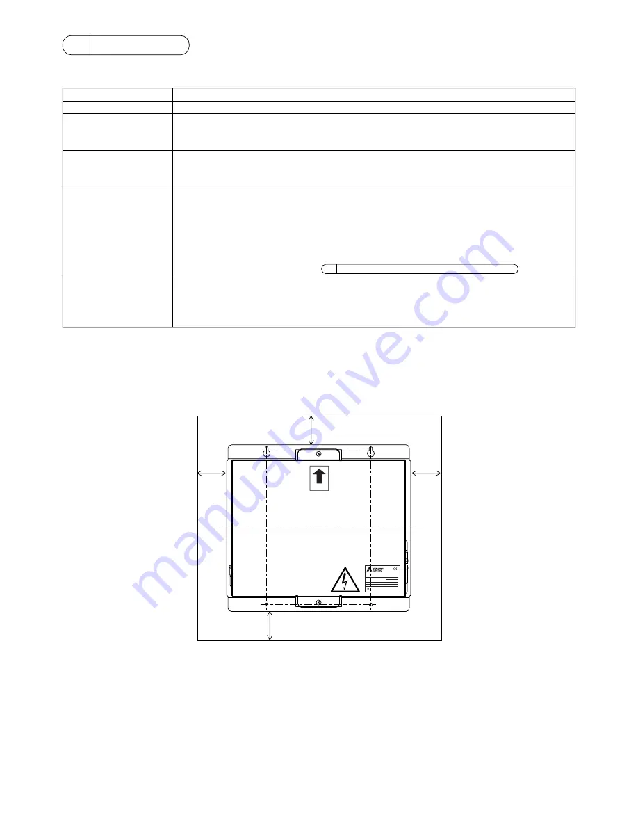
2. Installation space and the direction

PAC-SC50KUA Power supply unit is not waterproof. Therefore this unit shall be installed in a control panel box or similar. Please
prepare the control panel box with consideration given to installation space as shown in the Fig.3-1.
The unit should be also installed in vertical direction also indicated by the arrow marking on the cover as shown in the Fig.3-1

Fig.3-1

20

20

20

20

UP


POWER RATING

MODEL


WEIGHT

SERIAL  No.

2.11kg

POWER SUPPLY UNIT

MITSUBISHI ELECTRIC CORPORATION

PAC-SC50KUA

Содержание PAC-SC50KUA

Страница 1: ...his Installation Manual in a location that is easy to find Contents 1 Safety precautions 1 2 Product feature 2 1 Specification 2 2 Appearance 2 3 Installation 3 1 Parts prepared at site 3 2 Installation space and the direction 3 3 Unit installation 4 4 Wiring 4 1 Cover Removal and Installation 4 2 Power line 5 3 DC Power Supply and M NET Transmission Line 5 5 Allowable length of M NET transmission...

Страница 2: ......

Страница 3: ...ame area Ensure that installation work is done correctly follow ing this installation manual Any deficiency caused by installation may result in an elec tric shock or fire All electrical work must be performed by a licensed tech nician according to local regulations and the instruc tions given in this manual Any lack of electric circuit or any deficiency caused by in stallation may result in an el...

Страница 4: ...uirement Input voltage AC220V AC240V 0 2A Maximum loading 50 60Hz Single phase Fuse 2 0A Time delay type IEC127 2 S S 5 Output voltage current M NET DC22V 24V 0 45A Maximum loading DC power supply DC12V 0 9A Maximum loading Load capacity Number of the loading unit G 50A Central Controller 1 unit Environmental condition Temperature Operating 0 40 C Non operating 20 60 C Humidity 30 90 RH No condens...

Страница 5: ...φ1 2mm φ1 6mm CVVS 1 25mm2 2mm2 CPEV PE insulated PVC jacketed shielded communication cable CVVS PVC insulated PVC jacketed shielded control cable Cable length Please refer to section 5 Allowable length of M NET transmission line The DC power cable should comply with both local standards as well as the power requirement of the unit Recommended type 0 75mm2 2 0mm2 Cable length Within 10m 2 Installa...

Страница 6: ...y fail 1 Cover Removal and Installation When removing the cover remove the 2 mounting screws and remove the cover When installing the cover install the cover by tightening the 2 screws Fig 4 1 UP POWER RATING MODEL WEIGHT SERIAL No 2 11kg POWER SUPPLY UNIT MITSUBISHI ELECTRIC CORPORATION PAC SC50KUA M4 UP POWER RATING MODEL WEIGHT SERIAL No 2 11kg POWER SUPPLY UNIT MITSUBISHI ELECTRIC CORPORATION ...

Страница 7: ...ine The DC power line and M NET transmission line connect as shown in Fig 4 3 The DC power line has a 12VDC and a GND polarity Connect it to the terminals in accordance with the polarity Connect the M NET transmission line to the A B non polarity and S shield terminal block Fig 4 3 GND 12VDC 12V 24V S B A N L R GND 12VDC S B A TB3 Fix the power line TB2 Within 10m DC power supply line DC12V Polari...

Страница 8: ... r4 r8 may not consider to the total length Central controller Power supply unit DC Power supply DC12V Length max 10m Outdoor unit Outdoor Indoor Indoor Indoor Indoor Indoor Indoor Indoor Indoor Remote controller Remote controller M NET transmission line Centralized control line M NET transmission line Indoor control line L2 L3 L4 L1 L5 r 1 r 2 r3 r 4 r5 r6 r8 r7 Indoor CAUTION Both of PAC SC50KUA...

Страница 9: ......

Страница 10: ......

Страница 11: ......

Страница 12: ...OUCHI CHIYODA KU TOKYO 100 8310 JAPAN This product is designed and intended for use in the residential commercial and light industrial environment The product at hand is based on the following EU regulations Low Voltage Directive 73 23 EEC Electromagnetic Compatibility Directive 89 336 EEC ...

Отзывы: