56
4 STARTUP
4.3 Troubleshooting at startup
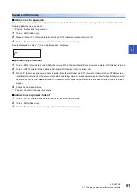
Investigating the cause of a position mismatch
If a position mismatch occurs, check (a) output pulse counter Q, (b) cumulative command pulse P, (c) cumulative feedback
pulse C, and (d) machine stop position M in the above diagram. In addition, causes A, B, and C indicate the causes of the
position mismatch. For example, Cause A indicates that noise had entered the wiring between the controller and servo
amplifier, causing the command input pulses to be miscounted.
In a normal status without the position mismatch, the following relationships are established.
• Q = P (Output counter = Cumulative command pulses)
• When [Pr. PA21.3] is set to "0"
• When [Pr. PA21.3] is set to "1"
• When [Pr. PA21.3] is set to "4"
• C •
Δℓ
= M (Cumulative feedback pulses × Travel distance per pulse = Machine position)
Check the position mismatch in the following order.
• When Q
≠
P
Noise entered the pulse train signal wiring between the controller and servo amplifier, causing command input pulses to be
miscounted. (Cause A)
Check the following items and take the following measures.
Check how the shielding is done.
Change the open collector type to the differential line driver type.
Wire separately from the strong electric circuit.
Install a data line filter. (
MR-J5 User's Manual (Hardware))
Change the setting of [Pr. PA13 Command pulse input form].
•
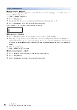
During operation, SON (Servo-on), LSP (Forward rotation stroke end), or LSN (Reverse rotation stroke end) was switched off,
or CR (Clear) or RES (Reset) was switched on. (Cause C)
• When C •
Δℓ
≠
M
Mechanical slippage occurred between the servo motor and machine. (Cause B)
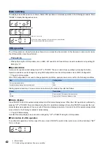
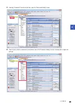
Investigation by using MR Configurator2.
The reason that the servo motor does not rotate can be investigated via MR Configurator2.
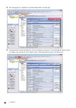
The cause that the servo motor fails to rotate is acquired from the servo amplifier of the target axis, and displayed on "No
Motor Rotation". The window will remain blank when no cause exists. "- - - -" is displayed when off-line or the cause cannot be
acquired.
Q
P
C
M
L
[Pr. PA05], [Pr. PA06],
[Pr. PA07], [Pr. PA21]
Controller
Servo amplifier
Machine
(a) Output
pulse counter
Servo motor
Electronic gear
(d) Machine stop
position M
(b) Cumulative
command pulses
Cause B
Cause A
SON (Servo-on) input
LSP/LSN (Stroke end) input
Encoder
Cause C
(c) Cumulative
feedback pulses
CMX [Pr. PA06]
CDV [Pr. PA07]
P
= C (Cumulative command pulses × Electronic gear = Cumulative feedback pulses)
67108864
FBP [Pr. PA05]
P •
= C
CMX [Pr. PA06]
CDV [Pr. PA07]
P •
× 16 = C
CMX
CDV
≠
C
When P
Содержание Melservo MR-J5-A
Страница 1: ...MR J5 A User s Manual Introduction MR J5 _A_ Mitsubishi Electric AC Servo System ...
Страница 2: ......
Страница 75: ...6 COMPLIANCE WITH GLOBAL STANDARDS 6 5 Compliance with the China RoHS directive 73 6 MEMO ...
Страница 79: ......

