40
3 STRUCTURE
3.2 Switch setting and display of the servo amplifier
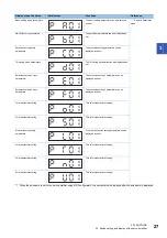
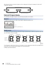
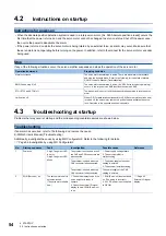
When the value of the servo parameter is negative, a minus is displayed in the first digit. The example for in the case of "-
1234567890" is displayed.
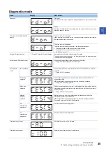
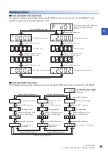
External I/O signal display
The on/off states of the digital I/O signals connected to the servo amplifier can be confirmed.
Operation
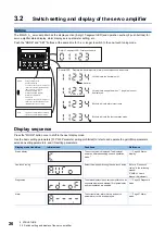
The display screen after power-on is shown. Press "MODE" to display the diagnostic screen.
Display content
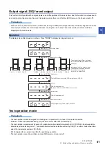
The 7-segment LED segments and CN3 connector pins correspond as shown below. The CN3-13 pin and CN3-14 pin can be
used on the MR-J5-_A-RJ servo amplifiers.
The LED segments corresponding to the pins are lit to indicate on, and are extinguished to indicate off. For pin signals in each
control mode, refer to "Connectors and pin assignments" in the following manual.
MR-J5 User's Manual (Hardware)
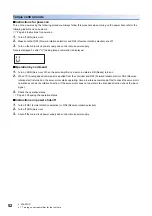
Press the "MODE" button once.
Press the "MODE" button once.
Press the "MODE" button once.
Press the "UP" button twice.
External I/O signal display screen
CN3-16
CN3-41
CN3-22
CN3-48
CN3-19
CN3-15
CN3-44
CN3-43
CN3-23
CN3-25
CN3-49
CN3-24
CN3-18
CN3-17
CN3-33
CN3-45
CN3-10/CN3-37
CN3-35/CN3-38
CN3-42
CN3-13
CN3-14
Input signal
Always lit
Output signal
Light on: on
Light off: off
Содержание Melservo MR-J5-A
Страница 1: ...MR J5 A User s Manual Introduction MR J5 _A_ Mitsubishi Electric AC Servo System ...
Страница 2: ......
Страница 75: ...6 COMPLIANCE WITH GLOBAL STANDARDS 6 5 Compliance with the China RoHS directive 73 6 MEMO ...
Страница 79: ......

