12
1 SPECIFICATIONS
1.5 Function block diagram
1.5
Function block diagram
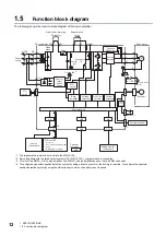
The following shows the function block diagram of this servo amplifier.
*1 The regenerative resistor is not built into the MR-J5-10A_.
*2 Servo amplifiers with the rated output symbol of 70 (MR-J5-70A_) or greater have a cooling fan.
*3 This is for the MR-J5-_A-RJ servo amplifier. The MR-J5-_A servo amplifier does not have a CN2L connector.
*4 To configure an absolute position detection system by using a direct drive motor, the battery is required. To configure the absolute
position detection system by using the HK series servo motor, the battery is not required.
U
U
U
L11
L21
N-
C
D
L3
L2
L1
MC
MCCB
U
V
W
U
V
W
P3
P4
P+
+
+
B
RA
B1
B2
CN4
M
CN2
CN8
CN5
CN6
I/F
USB
D/A
A/D
USB
CN3
*1
CN2L
*3
E
Power factor improving
DC reactor
Regenerative
option
Servo amplifier
Servo motor
Diode
stack
Dynamic
brake circuit
Relay
Current
detector
Power
supply
Regenerative
TR
Charge
light
Cooling fan
*2
Electromagnetic
brake
Control
circuit
power
supply
STO
circuit
STO
switch
Encoder
Overcurrent
protection
Base
amplifier
Voltage
detection
Current
detection
Step-
down
circuit
Control engine
Battery
*4
External encoder
D I/O control
Servo-on
Command pulse train input
Start
Malfunction, or others
Analog
(2 channels)
Personal
computer
Analog monitor
(2 channels)
24 V DC
Содержание Melservo MR-J5-A
Страница 1: ...MR J5 A User s Manual Introduction MR J5 _A_ Mitsubishi Electric AC Servo System ...
Страница 2: ......
Страница 75: ...6 COMPLIANCE WITH GLOBAL STANDARDS 6 5 Compliance with the China RoHS directive 73 6 MEMO ...
Страница 79: ......


