12 USING A FULLY CLOSED LOOP SYSTEM
12.5 Basic functions
435
12
About MR Configurator2
With MR Configurator2, the servo parameters can be checked if set correctly, and the servo motor and the load-side encoder
can be checked if operated properly.
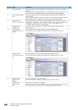
This section explains the Fully Closed Loop Diagnosis screen.
Symbol
Name
Explanation
Unit
(a)
Servo motor-side cumulative
feedback pulses
(after gear)
The feedback pulses from the servo motor encoder are counted and displayed.
(load-side encoder unit)
When the setting value exceeds 999999999, it starts from 0.
Click "Clear" to reset the value to "0".
In reverse rotation, the value is negative.
pulse
(b)
Servo motor-side droop
pulses
Droop pulses of the deviation counter between a servo motor-side position and a command are
displayed.
In reverse rotation, the value is negative.
pulse
(c)
Cumulative command pulses
Position command input pulses are counted and displayed.
Click "Clear" to reset the value to "0".
Under reverse command, the value is negative.
pulse
(d)
Load-side encoder cumulative
feedback pulses
The feedback pulses from the load-side encoder are counted and displayed.
When the setting value exceeds 999999999, it starts from 0.
Click "Clear" to reset the value to "0".
In reverse rotation, the value is negative.
pulse
(e)
Load-side encoder droop
pulses
Droop pulses of the deviation counter between a load-side position and a command are displayed.
In reverse rotation, the value is negative.
pulse
(f)
Servo motor-side cumulative
feedback pulses
(before gear)
The feedback pulses from the servo motor encoder are counted and displayed.
(Servo motor encoder unit)
When the setting value exceeds 999999999, it starts from 0.
Click "Clear" to reset the value to "0".
In reverse rotation, the value is negative.
pulse
(g)
Encoder information
The load-side encoder information is displayed.
The display contents differ depending on the load-side encoder type.
• ID: The ID No. of the load-side encoder is displayed.
• Data 1: For an incremental type linear encoder, the counter from powering on is displayed. For an
absolute position type linear encoder, absolute position data is displayed.
• Data 2: For the incremental type linear encoder, the distance (number of pulses) from the reference
mark (Z-phase) is displayed. For the absolute position type linear encoder, "00000000" is displayed.
(h)
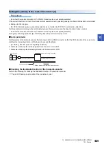
Parameter Setting
(Polarity)
"+" is displayed for the address increasing direction in the servo motor CCW direction, and "-" is
displayed for the address decreasing direction in the servo motor CCW direction.
(m)
(n)
(c)
(j)
(i)
(k)
(g)
(f)
(b)
(e)
(h)
(l)
(a)
(d)
Содержание Melservo-J5 MR-J5 Series
Страница 1: ...MR J5 User s Manual Hardware MR J5 _G_ MR J5W_ _G_ MR J5 _A_ Mitsubishi Electric AC Servo System ...
Страница 2: ......
Страница 441: ...12 USING A FULLY CLOSED LOOP SYSTEM 12 7 Absolute position detection system 439 12 MEMO ...
Страница 445: ......

