

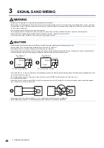


3 SIGNALS AND WIRING
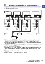
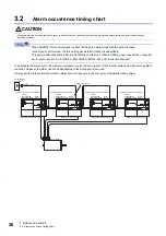
3.2 Alarm occurrence timing chart
27
3
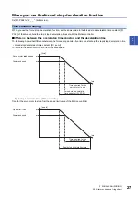
When you use the forced stop deceleration function
Set [Pr. PA04] to "2 _ _ _" (initial value).
Time constant setting
When you use the forced stop deceleration function, set the same value in the forced stop deceleration time constant [Pr.
PC24] of the drive unit and the rapid stop deceleration time set with the Motion controller.
■
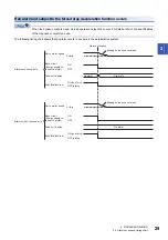
Difference between the deceleration time constant and the deceleration time
The following shows the difference between the forced stop deceleration time constant and the rapid stop deceleration time.
• Forced stop deceleration time constant (Drive unit)
The time for the servo motor to stop from the rated speed
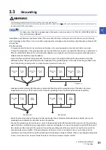
• Rapid stop deceleration time (Motion controller)
Time for the servo motor to stop from the speed limit value of the Motion controller
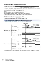
Servo motor rated speed
Time required for the
servo motor to stop
Command speed
Forced stop deceleration
time constant [Pr. PC24]
[r/min]
[ms]
Speed limit value
Rapid stop deceleration time
[pulse/s]
[ms]
Time required for the
servo motor to stop
Command speed
Содержание Melservo-J4 MR-J4-DU*B4-RJ100 Series
Страница 1: ...General Purpose AC Servo SSCNET III H Interface Drive Unit Instruction Manual MR J4 DU_B4 RJ100 ...
Страница 2: ......
Страница 75: ...9 USING STO FUNCTION 73 9 MEMO ...
Страница 81: ...11 APPENDIX 11 1 Analog monitor 79 11 MEMO ...
Страница 85: ......