


162
16 TROUBLESHOOTING
16.7 Checking method
Check the LED status and take the corresponding corrective actions.
If the LED does not turn ON in synchronization with the utility display or execution status of the board, LED failure may occur.
In this case, replace the board.
MODE LED is turned OFF or flashing
MODE LED is an LED which does not exist on the board. Check the status with the LED display on the "CC IE Field
Diagnostics" screen. (
Page 127 Selected station communication status monitor)
When the MODE LED is turned OFF, it is in the offline mode. When the MODE LED is flashing, it is in the test mode.
D LINK LED is turned OFF or flashing
D LINK LED is an LED which does not exist on the board. Check the status with the LED display on the "CC IE Field
Diagnostics" screen. (
Page 127 Selected station communication status monitor)
When the D LINK LED is turned OFF, both cyclic transmission and transient transmission of the board are stopped.
When the D LINK LED is flashing, the cyclic transmission of the board is stopped, or communication route is consecutively
built because the network communication route is unstable.
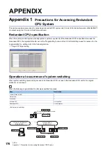
LED
Status
Description
Reference
RUN
ERR.
SD
RD
ON
OFF
OFF
OFF
Operating normally.
(Data send/receive is not performed.)
Corrective action unnecessary
ON
OFF
ON
Operating normally. (Sending data)
ON
OFF
ON
Operating normally. (Receiving data)
ON
ON/Flash
Communication error has occurred.
Page 152 Communication error
(ERR. LED is ON/Flashing)
OFF
OFF
OFF
OFF
A hardware failure or a board WDT error has
occurred.
Page 150 Hardware error or board
WDT error
The driver is not started.
Page 151 Driver does not start
Flash
ON
Driver WDT error has occurred.
Flash
ON
PCI bus/PCI Express bus error has occurred.
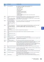
LED
Status
Description
Reference
P1, P2
L ER
OFF
Operating normally.
• The module received normal data.
• The board does not perform loopback.
• Linkup in progress.
Corrective action unnecessary
LINK
ON
L ER
ON
• The module received abnormal data.
• The board is performing loopback.
Page 163 L ERR. LED/L ER LED is
turned ON
LINK
OFF
Linkdown in progress.
Page 163 LINK LED is turned OFF
Item
Corrective action
Is the mode set to the online mode?
Change the mode to the online mode. (
Page 99 Setting Network Parameter)
Is the board hardware operating normally?
Perform the board test. (
Item
Corrective action
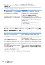
Is the master station connected to the network and operating normally?
• If an error has occurred in the master station, solve the error.
• Check if the master station is performing data link with CC-Link IE Field Network
diagnostics, and perform the corrective action. (
• When the master station and submaster station are the module other than the
MELSEC iQ-R series, and there is a local station of the MELSEC iQ-R series
module, refer to the following section. (
connecting the MELSEC iQ-R series module)
Are the connected other stations normal?
Check if the other station's power is turned ON.
Are cables and wiring normal?
• Check the cables and wiring. (
Page 157 Checking cables and wiring)
• Perform a loop test. (
• Perform a cable test. (
Is the loopback function enabled for the master station?
Configure a ring topology without connecting the switching hub.
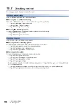
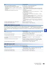
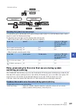
L ER LED
LINK LED
RJ45 connector
Содержание MELSEC Q80BD-J71GF11-T2
Страница 2: ......
Страница 6: ...4 Disposal Precautions CAUTION When disposing of this product treat it as industrial waste ...
Страница 118: ...116 12 MONITORING MEMO ...
Страница 140: ...138 14 MELSEC DATA LINK LIBRARY MEMO ...
Страница 142: ...140 15 PROGRAMMING 15 1 Precautions on Programming MEMO ...
Страница 243: ...241 I U Utility 83 ...
Страница 247: ......


