


75
CHAPTER 3 SPECIFICATIONS AND FUNCTIONS
3
3.
4 Spec
ificat
ions
o
f I
nput
/O
ut
put
I
n
te
rf
aces wit
h Ex
te
rn
al
Devices
Drive unit READY
(READY)
1A11
1B11
2A11
2B11
• This signal turns ON when the drive unit is normal and can accept the feed pulse.
• The LD75 checks the drive unit READY signal, and outputs the OPR request if the
system is not in the READY state.
• When the drive unit is inoperable, such as if an error occurs in the drive unit's control
power supply, this signal will turn OFF.
• If this signal is turned OFF during positioning, the system will stop. The system will not
start even if this signal is turned ON again.
• When this signal turns OFF, the OPR complete signal will also turn OFF.
Drive unit READY common
(RDYCOM)
1A12
1B12
2A12
2B12
• Common for drive unit READY signal.
Deviation counter clear
(CLEAR)
1A13
1B13
2A13
2B13
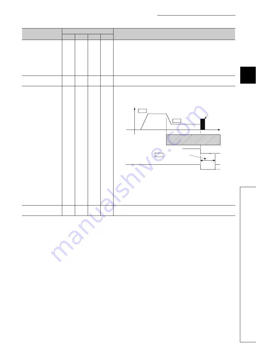
• This signal is output during machine OPR. (Note that it is not output during the count
method 2).)
(Example) When machine OPR is carried out in the stopper 2) method.
• The output time of the deviation counter clear signal is set in "[Pr.55] Deviation counter
clear signal output time".
• Use the drive unit that can reset the droop pulse amount in the internal deviation
counter when the LD75 turns this signal ON.
(Note) The deviation counter clear is a signal output by the LD75 during machine OPR. It
cannot be output randomly by the user.
Deviation counter clear
common (CLRCOM)
1A14
1B14
2A14
2B14
• Common for deviation counter clear signal
Signal name
Pin No.
Signal details (Negative logic is selected by external I/O signal logic selection)
AX1
AX2
AX3
AX4
OFF
ON
OFF
ON
CLEAR
OPR speed
Creep speed
Near-point dog
Zero signal
Time
Speed
After feed pulse output stops
Stopper
Pr.46
Pr.47
Pr.55 Deviation counter
clear signal output time
Содержание MELSEC-L LD75D
Страница 1: ...MELSEC L LD75P LD75D Positioning Module User s Manual LD75P1 LD75P2 LD75P4 LD75D1 LD75D2 LD75D4 ...
Страница 2: ......
Страница 11: ...9 Memo ...
Страница 47: ...45 CHAPTER 2 SYSTEM CONFIGURATION 2 2 1 General Image of System 1 When connected to a CPU module ...
Страница 176: ...174 ...
Страница 264: ...262 ...
Страница 266: ...264 ...
Страница 267: ...265 CHAPTER 6 PROGRAM USED FOR POSITIONING CONTROL 6 6 4 Positioning Program Examples ...
Страница 268: ...266 ...
Страница 269: ...267 CHAPTER 6 PROGRAM USED FOR POSITIONING CONTROL 6 6 4 Positioning Program Examples ...
Страница 270: ...268 ...
Страница 271: ...269 CHAPTER 6 PROGRAM USED FOR POSITIONING CONTROL 6 6 4 Positioning Program Examples ...
Страница 272: ...270 Z ABRST1 instruction execution ...
Страница 273: ...271 CHAPTER 6 PROGRAM USED FOR POSITIONING CONTROL 6 6 4 Positioning Program Examples ...
Страница 278: ...276 ...
Страница 279: ...277 CHAPTER 6 PROGRAM USED FOR POSITIONING CONTROL 6 6 4 Positioning Program Examples ...
Страница 280: ...278 ...
Страница 281: ...279 CHAPTER 6 PROGRAM USED FOR POSITIONING CONTROL 6 6 4 Positioning Program Examples ...
Страница 282: ...280 ...
Страница 283: ...281 CHAPTER 6 PROGRAM USED FOR POSITIONING CONTROL 6 6 4 Positioning Program Examples ...
Страница 284: ...282 ...
Страница 285: ...283 CHAPTER 6 PROGRAM USED FOR POSITIONING CONTROL 6 6 4 Positioning Program Examples ...
Страница 286: ...284 ...
Страница 287: ...285 CHAPTER 6 PROGRAM USED FOR POSITIONING CONTROL 6 6 4 Positioning Program Examples ...
Страница 316: ...314 Memo ...
Страница 685: ...683 APPENDICES A Appendix 1 Function Update Appendix 1 1 Function comparison Memo ...
Страница 738: ...736 Memo ...
Страница 806: ...804 5 LD75D2 Unit mm 6 LD75D4 Unit mm 45 4 90 4 95 4 45 45 DIN rail center 45 4 90 4 95 4 45 45 DIN rail center ...
Страница 817: ......


