background image

Operation of Teaching Box (R32TB)

Select a menu item

FR series

 6 - 7

6.3 

Select a menu item

There are two ways to call up a menu:

Select a menu by entering a number

Select the menu with the cursor an press the [EXE] key

Running

Both possibilities are displayed in the following example by selecting menu item "1. FILE/EDIT".

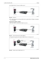
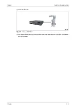
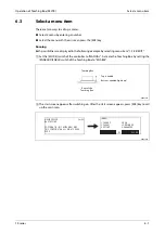
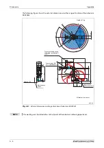
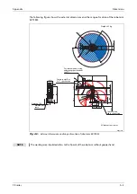
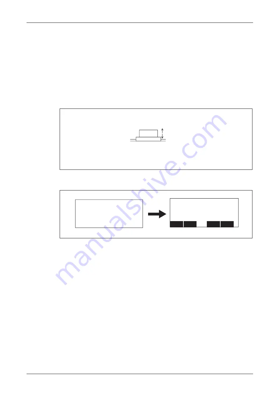
Set the [MODE] switch of the controller to "MANUAL". Activate the Teaching Box by setting the


[ENABLE/DISABLE] switch of the Teaching Box to "ENABLE".

The start screen appears after switching on. After the start screen appears, press [EXE] key to call 
up the main men.

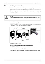
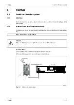
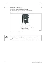
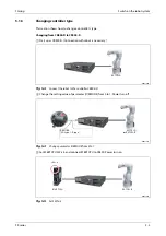
R002757E

R002759E


Top: disabled


Bottom: enabled (lights up)

Teaching Box

Rear of the

Teaching Box

MELFA CR800-D                                          Ver. S3

RH-3FH5515-D

COPYRIGHT (C) 2011  MITSUBISHI  ELEC

TRIC  CORPORATION  ALL  RIGHTS  RESE

RVED

<MENU>

1. FILE/EDIT                      2. RUN

3. PARAM.                         4. ORIGIN/BRK

5. SET/INIT.                       6. ENHANCED

CLOSE

123

Содержание MELFA RH-FRH-D

Страница 1: ...MITSUBISHI ELECTRIC INDUSTRIAL AUTOMATION MITSUBISHI ELECTRIC MELFA Industrial robots Installation description RV FR D RH FRH D RV FR R RH FRH R Art No 325252 20 04 2020 Version C Versionsprüfung ...

Страница 2: ......

Страница 3: ...ons A 02 2018 pdp gb B 07 2019 pdp gb Section 1 4 Procedure for enabling the safety diagnosis function STO func tion added C 04 2020 pdp gb Section 4 3 1 Section 4 3 3 Classification of functions using external input output signals added Former section 1 4 was shifted to Section 4 3 3 Safety diagno sis function Test pulse diagnosis ...

Страница 4: ......

Страница 5: ...ng the installation and operation of the units described in this manual then please do not hesitate to contact your responsible sales office or sales partner see cover page Current information as well as answers to frequently asked questions are located on the internet at http www mitsubishi automation com MITSUBISHI ELECTRIC EUROPE B V reserves the right to make technical alterations to this manu...

Страница 6: ......

Страница 7: ...softwareornon observanceofthewarninginstructionscontained in this manual or attached to the product may result in serious damage injury to property and per sons Only those auxiliary units and expansion units recommended by MITSUBISHI ELECTRIC may be used together with the FR robot system Any and all other use is determined as not in accordance to the instructions The industrial robots may only be ...

Страница 8: ...551 Regulations for transformers VDE 0700 Safety of electrical devices for domestic and similar uses VDE 0860 Safety regulations for mains operated electronic devices and their accessories for domestic and similar uses Fire protection regulations Accident prevention regulations VBG No 4 Electrical plants and equipment E CAUTION A safety manual is included with the robot This manual deals with the ...

Страница 9: ...f the robot The individual instructions mean the following P DANGER Meansthatthereisadangertolifeandhealthoftheuser e g fromelectricalvoltage e g when the appropriate safety measures have not been taken E CAUTION Is a warning of possible damages to the robot its periphery or other valuable property if the appropriate safety measures are not taken ...

Страница 10: ...dous dangerous operating conditions must arise when doing this even temporarily If necessary force an EMERGENCY STOP EMERGENCY STOP equipment compliant to EN 60204 IEC 204 VDE 0113 must remain effec tive during all applications Unlocking the EMERGENCY STOP equipment must never result in uncontrolled movements of the robot arm P DANGER Some of the robot arms are made of plastic The robot arm does n...

Страница 11: ...echanical end stops when an articulated robot is inautomaticmodethentheplasticbuffersoftheendstopsmustbereplaced Otherwise the reduction gearing may be severely damaged on the next collision Please contact your Mitsubishi Electric partner to replace the buffers When the power supply is interrupted then the brakes grip the robot arm If this happens the robot arm may deviate from its predefined trav...

Страница 12: ...nstructions are steps that must be carried out in their exact sequence during startup op eration maintenance and similar operations They are numbered consecutively black numbers in white circles Text Text Text Use of footnotes in tables Instructionsintablesareexplainedinfootnotesunderneaththetables insuperscript Thereisafoot note character at the appropriate position in the table in superscript If...

Страница 13: ...2 System overview 2 1 Scope of delivery 2 1 2 1 1 FR D series 2 1 2 1 2 FR R series 2 2 2 2 System configuration 2 3 2 2 1 FR D series 2 3 2 2 2 FR R series 2 4 2 2 3 Components of the robot arm 2 5 2 3 Controller CR800 2 9 2 3 1 Front side 2 9 2 3 2 Rear 2 11 2 4 Robot CPU FR R series only 2 12 2 5 Teaching Box 2 13 2 5 1 R32TB 2 13 2 5 2 R56TB 2 15 ...

Страница 14: ...ling the CR800 controller 3 25 3 5 Installation of robot CPU R16RTCPU 3 26 3 5 1 Installation and removal of modules 3 27 3 6 Grounding the robot system 3 30 4 Connection 4 1 Connection of the connection cable 4 1 4 1 1 Connect the robot arm to the CR800 controller 4 1 4 1 2 Connection of robot CPU to the drive unit 4 8 4 2 Mains connection and grounding 4 9 4 2 1 CR800 controller 4 9 4 3 EMERGENC...

Страница 15: ... 6 7 6 4 Move robot in JOG mode 6 9 6 4 1 JOG modes 6 9 7 Troubleshooting and maintenance instructions 7 1 Faults in automatic mode 7 1 7 2 Troubleshooting 7 1 7 3 Error diagnosis 7 2 7 4 Replace the fuses 7 3 7 4 1 Fuse and error messages 7 3 7 4 2 Fuse of power supply of pneumatic gripper hand 7 3 7 5 Instructions on maintenance 7 4 A Appendix A 1 Dimensions A 1 A 1 1 Working areas of the robot ...

Страница 16: ...Contents X ...

Страница 17: ...o the Teaching Box R32TB This manual applies to the following robots and controllers Series Model Construction Handling weight kg Controller FR D RV 2FR B D Vertical articulated arm 2 CR800 D RV 2FRL B D 2 RV 4FRM D 4 RV 4FRLM D 4 RV 7FRM D 7 RV 7FRLM D 7 RV 7FRLLM D 7 RV 13FRM D 13 RV 13FRLM D 13 RV 20FRM D 20 RH 1FRHR D SCARA 1 RH 3FRHR D 3 RH 3FRH D 3 RH 6FRH D 6 RH 12FRH D 12 RH 20FRH D 20 FR ...

Страница 18: ...ecification Sxx special model Controller type D CR800 D R CR800 R empty standard model IP 40 M oil mist specifications IP 67 C clean room model ISO class 3 empty standard type L or LL long arm type RV 2FR and RV 2FRL only empty J2 J3 J5 axis has brake B all axes with brake Series FR FR series Load bearing capacity in kg RV vertical articulated arm robot ...

Страница 19: ...00 D R CR800 R empty standard model C clean room model M oil mist specifications Arm lengths of ballscrew e g 12 120 mm 15 150 mm 20 200 mm 34 340 mm 35 350 mm 45 450 mm Arm lengths e g 35 350 mm 45 450 mm 55 550 mm 70 700 mm 85 850 mm 100 1000 mm Installation type empty floor R ceiling Series FRH FRH series Load bearing capacity in kg RH Horizontal articulated arm robot ...

Страница 20: ...ivities when operating the robot must be clearly defined and observed to ensure that there are no unclarities or unclear duties regarding the safety aspects For all work relating to the installation startup equipping fitting operation changes to oper ating conditions and modes of operation maintenance inspection and repairs the switch off procedures stipulated in the manual must be observed The po...

Страница 21: ...FR HF interference Do not use when there are voltage peaks on the mains supply greater than 1000 V and longer than 1 μs there are large frequency inverters transformers magnetic switches or welding devices in the vicinity there are radios or televisions in the vicinity Temperature Humidity Do not use when the ambient temperature is above 40 C or below 0 C the robot is subjected to direct sunlight ...

Страница 22: ...Environmental conditions for operation Introduction 1 6 ...

Страница 23: ...rbasicoperationoftherobotaredescribedinthischapter Optionsandsparepartsarelisted in the technical manual 2 1 Scope of delivery 2 1 1 FR D series R002680E Fig 2 1 Scope of delivery of robot systems RV FR D and RH FRH D RV 2 4 7 13 20FR D R SCARA Fixing screws with washers and snap rings Transport locks Technical documentation Controller Cable Vertical articulated robot arm or ...

Страница 24: ... R series R002681 Fig 2 2 Scope of delivery of robot systems RV FR R and RH FRH R RV FR R RH FRH R SCARA Fixing screws with washers and snap rings Transport locks Technical documentation Drive unit Vertical articulated robot arm or Cable Robot CPU ...

Страница 25: ... controllers are available for the different systems CR800 D controller CR800 R controller CR800 drive unit and Robot CPU R16RTCPU 2 2 1 FR D series R002682E Fig 2 3 Configuration of an FR D series robot system NOTE The Teaching Box is an optional extra It is required for basic operation of the robot Vertical articulated robot arm SCARA Cable Controller Teaching Box optional or ...

Страница 26: ... R series R002683E Fig 2 4 Configuration of an FR R series robot system NOTE The Teaching Box is an optional extra It is required for basic operation of the robot Vertical articulated robot arm SCARA Cable Drive unit Teaching Box optional Robot CPU or ...

Страница 27: ...latedarmrobotRV 2FR 4FR 7FR 13FR 20FR Name of axis Meaning J1 axis Base axis J2 axis Shoulder axis J3 axis Elbow axis J4 axis Rotating forearm axis J5 axis Wrist tilting axis J6 axis Wrist rotating axis Tab 2 1 Overview of axis names J3 axis J6 axis Wrist J4 axis Forearm Arm 2 Elbow block Upper arm Arm 1 J2 axis Base J1 axis Shoulder J5 axis Elbow Mechanical interface ...

Страница 28: ...System configuration System overview 2 6 RH 1FRHR5515 R002752E Fig 2 6 Components of the robot arm in the SCARA RH 1FRHR5515 J2 axis J3 axis Shaft Arm 1 Arm 2 Base J1 axis J4 axis Brake release switch ...

Страница 29: ...iguration FR series 2 7 RH 3FRHR3515 12 R002249E Fig 2 7 Components of the robot arm RH 3FRHR3515 12 㻶㻠 㻶㻞 㻶㻟 㻶㻝 䝤䝺䞊䜻ゎ㝖䝇䜲䝑䝏 䝧䞊䝇 䝅䝱䝣䝖 䠄 㠃䠅 䠍䜰䞊䝮 㻞䜰䞊䝮 J3 axis Brake release switch J4 axis Shaft J2 axis Base J1 axis Arm 1 Arm 2 Rear ...

Страница 30: ...m configuration System overview 2 8 RH 3FRH 6FRH 12FRH 20FRH R002685E Fig 2 8 Components of the robot arm RH 3FRH 6FRH 12FRH 20FRH J2 axis J3 axis Shaft Arm 1 Arm 2 Base J1 axis J4 axis Brake release switch ...

Страница 31: ...he robot CPU OPT2 Connector for communication with another controller AXIS Connector for additional axis connection PC Connector for communication with a personal computer EXT2 Connector for function extension Tab 2 2 Overview of components on the front side of the controller CR800 1 Air intake for fan LED Details POWER Indicates the control power status On Control power ON Off Control power OFF A...

Страница 32: ...lter cover Dustproof dust filter cover An air filter is provided inside the filter cover Option SLOT 1 Option card slots must be covered when not used Option SLOT 2 FG terminal Option card cable terminals for grounding No Name Function Tab 2 2 Overview of components on the front side of the controller CR800 2 ...

Страница 33: ...rminal M4 2 Terminals for grounding CN1 connector Machine cable connector CNUSR11 connector Robot I O cable connectors including emergency stop connector CNUSR12 connector Tab 2 3 Components on the rear of the controller CR800 Air exhaust Air exhaust no use Number of phase ACIN cable Single phase Terminal M5 cable length 3 m Three phase Terminal M5 cable length 3 m ...

Страница 34: ...ix LED dis play Status and alarm display CN1 connector Connect the SSCNETIII H cable between the OPT1 connector on the controller and this connector Network connector Connector for Ethernet communication EMG connector Unused MPG connector Unused RIO connector Unused EXT I F Unused Tab 2 4 Overview of robot CPU components LED CPU status READY ERROR OFF ON Power is off or a hardware error occurred F...

Страница 35: ...ay The status of the program or the robot arm is displayed on the LCD Status display The LED displays the status of the robot or the Teaching Box F1 F2 F3 F4 key Run the functions currently shown on the display FUNCTION key Toggle the displayed functions STOP key Cancel the running program and stop the robot This function is the same as the function of the STOP key on the control panel of the cont...

Страница 36: ...ops up the hand menu CHARACTER key Calls up the Edit menu and switches between numbers and letters e g when edit ing position data RESET key Acknowledges an error code A program is reset when used together with the EXE key key Moves the cursor in the appropriate direction CLEAR key Deletes the character at the cursor position EXE key Enter data or move the robot in direct mode Data key Overwrites ...

Страница 37: ...witch with locking function for EMERGENCY STOP After pressing this the robot is immediately stopped irrespective of the respective operating condition The pushbutton is once more unlocked by turning it to the right Stylus inserted into hous ing The touchscreen can be operated with this stylus It is contained in a slot in the housing of the operator device and should be stored there after being use...

Страница 38: ...lds using these arrow keys OK key Accept the settings in the current menu or entry field using this key CANCEL key Reject the settings in the current menu or entry field using this key Multi grip hand gripper The multi grip hand gripper provides for a sure and comfortable grip of the opera tor device and is suitable both for right and left handed operation Three step switch The three step enable s...

Страница 39: ...the floor as shown in Use a knife or similar object to open the packaging tape Pull the inner packaging out of the box horizontally as shown in Set the robot arm upright together with the inner packaging as shown in Open the inner packaging as shown in and remove the robot Transport the robot arm to the place of installation as described in Section 3 2 E CAUTION Always unpack the robot only on a s...

Страница 40: ... in Using both hands remove the upper part of the packaging as shown in Remove the four screws with which the base is screwed onto the lower section Transport the robot arm to the place of installation as described in Section 3 2 NOTE Keep the packaging and transport locks for later transport R002270E Fig 3 2 Unpack articulated arm robot RV 4FR RV 7FR RV 13FR and RV 20FR 䐠ୖ䝤䝍㻌 ᘬ䛝ᢤ䛟㻌 䐟䝔䞊䝥 䝣䜷䞊䜽䝸䝣䝖䛾 ...

Страница 41: ...emove the four fixing screws with which the base is screwed onto the wooden frame see Transport the robot arm to the place of installation as described in Section 3 2 NOTE Keep the packaging and transport locks for later transport R002689E Fig 3 3 Unpack the SCARA robot RH 1FRHR5515 E CAUTION The robot must be transported without removing the transport lock or transportation tool Remove after inst...

Страница 42: ...g material cardboard in the inside Open the vinyl and confirm the hanging tools two places Hang the hook of the crane here two places Hoist with the crane and separate the robot arm together with packing material from the packing box Cut with scissors etc tape which fixed packing material and remove packing material Transport the robot arm to the place of installation as described in Section 3 2 N...

Страница 43: ...te till installation is completed Packing box Tape Upper cover Packing material Cardboard Robot arm base section Hanging tools Packing material Tape Fixingplate Cut the tape Remove the upper cover Remove the packing material Open the vinyl Hang the hook of the crane Hoist with crane and remove the packing material Unpacking is completed ...

Страница 44: ...n in Remove the four fixing screws with which the base is screwed onto the wooden frame see Transport the robot arm to the place of installation as described in Section 3 2 NOTE Keep the packaging and transport locks for later transport R002271E Fig 3 5 Unpack the SCARA robots RH 3 6 12 20FRH E CAUTION The robot must be transported without removing the transport lock A or supporting bracket B Remo...

Страница 45: ...g points are only for brief lifting pur poses Take care to prevent impacts to the robot arm during transport E CAUTION When carrying the robot arm always hold it by the designated holding points and Never try to lift the robot arm by its covers as this can cause damage NOTE Keep the transport locks and their fastening screws in a safe place for later transport R001764E Fig 3 6 Transporting the RV ...

Страница 46: ...to transport the robot arm The transport lock must not be removed before transport The fixing screws of the transport lock and the transport bracket must be removed after transport NOTE Keep the transport lock the transport angle and their appropriate fixing screws in a safe place for any later transport E CAUTION To avoid faults the wire rope of the crane must be attached as shown in Fig 3 7 or F...

Страница 47: ...t arm FR series 3 9 R002272E Fig 3 7 Fix the transport bracket RV 4FR and RV 7FR R002435E Fig 3 8 Fix the transport bracket RV 13FR and RV 20FR Transport lock Transport bracket Wire rope Transport lock Transport bracket Wire rope ...

Страница 48: ...n Fig 3 9 Always use four supporting ropes to transport the robot with a crane The robot should keep vertical not be horizontal It becomes the cause of the grease leakage or the trouble NOTE Keep the transport and support brackets as well as the transport lock and their fixing screws in a safe place for any later transport R002753E Fig 3 9 Fix the transport suspensions E CAUTION Also observe the a...

Страница 49: ... After installing the robot pull out the forks and remove the transportation tools and the transport lock E CAUTION The robot should keep vertical not be horizontal It becomes the cause of the grease leakage or the trouble NOTE Keep the transport tools as well as the transport lock and their fixing screws in a safe place for any later transport R002754E Fig 3 10 Fork insertion segment of the robot...

Страница 50: ...sporting the robot at a later time e g when changingtheinstallationlocation Iftherobotistransportedwithouttheattachedtransporttools and the transport lock or if it is transported in operating position then dangerous situations might arise due to a shifting of the centre of gravity during transport ...

Страница 51: ...t by using two wires Take care sufficiently not to give the interference and the shock with the installation stage etc NOTE Keep the transporting jigs the transport lock and their fixing screws in a safe place for any later transport R001782E Fig 3 11 Transporting the robot arm E CAUTION Alsoobservetheabove mentionedstepswhentransportingtherobotatalatertime e g when changing the installation locat...

Страница 52: ... in damages Use a dolly if transporting longer distances Only carry at the holding points for short periods of time Do not strain any covers Avoid knocks impact loads when transporting the robot arm Only remove the transport locks after installing the robot arm E CAUTION The transport locks must not be removed before transport Two persons are always required to carry the robot arm Always carry the...

Страница 53: ...e must be attached as shown in Fig 3 13 Always use four supporting ropes to transport the robot with a crane NOTE Keep the transport and support brackets as well as the transport locks and their fixing screws in a safe place for any later transport R002274E Fig 3 13 Fix the transport suspensions E CAUTION Alsoobservetheabove mentionedstepswhentransportingtherobotatalatertime e g when changing the ...

Страница 54: ...installed on a common assembly platform area The base area must be designed so that no distortion can occur even from the loads and vibrations emanating from the robot itself Only remove the transport locks after setting up the robot arm If the robot is mounted on the ceiling then the MEGDIR parameter must be changed Additional information on this parameter is contained in the operation and progra...

Страница 55: ...ace remainingatthe rearof the robot arm to connect the cable used and to replace the backup battery and also space for J1 axis belt in the right side And don t install the robot arm in the position where direct rays or the heat of lighting hits The skin temperature of the robot arm may rise and the error may occur Robot arm Fixture View from below Tab 3 1 Set up the robot arm 2 Fixing screws 4 M8 ...

Страница 56: ...ly remove the transportation tool and the transport locks after setting up the robot arm High loads and strains occur on the base area when operating the robot at high speeds Make sure that the base area is suitable for the high forces and moments as listed in Tab 3 4 Robot arm Fixture View from below RH 1FRHR5515 R002698E R002699E Tab 3 3 Set up the robot arm Load RH 1FRHR5515 Moment of tilt ML N...

Страница 57: ... average surface finish of the assembly surface should be Ra 6 3 μm If the surface is too rough then this may result in deviations in the position of the robot arm Toavoidpositiondeviations theperipheralequipmentthattherobotaccessesaswellastherobot arm itself should be installed on a common assembly platform area The base area must be designed so that no distortion can occur even from the loads an...

Страница 58: ...ation bolt from the bottom R002700E Fig 3 14 Set up the robot arm Load RH 3FRHR Moment of tilt ML Nm 380 Torsional moment MT Nm 410 Translational forces on horizontal plane FH N 920 Translational forces on vertical plane FV N 570 Tab 3 5 Reaction forces on the base area of the robot 㻲㼂 㻹㼀 㻲㻴 㻹㻸 㻲㻴 㻹㻸 㻲㻴 㻲㻴 㻲㼂 Installation side standard 4 9 fixing boreholes 2 M12 hole for hanging tool 4 M8 hole to ...

Страница 59: ...thatthereis enough space remainingatthe rearof the robot arm to connect the cable used and at side to replace the backup battery And don t install the robot arm in the position where direct rays or the heat of lighting hits The skin temperature of the robot arm may rise and the error may occur ...

Страница 60: ...se area must be designed so that no distortion can occur even from the loads and vibrations emanating from the robot itself Only remove the transport locks suspensions andsupporting brackets after setting up the robot arm High loads and strains occur on the base area when operating the robot at high speeds Make sure that the base area is suitable for the high forces and moments as listed in Tab 3 ...

Страница 61: ... forces on vertical plane FV N 380 2318 2500 Tab 3 7 Reaction forces on the base area of the robot E CAUTION When installingtherobot make surethatthereis enough space remainingatthe rearof the robot arm to connect the cable used and to replace the backup battery And don t install the robot arm in the position where direct rays or the heat of lighting hits The skin temperature of the robot arm may ...

Страница 62: ...ling and set up of the controller 3 4 1 Transport the controller E CAUTION Carry the controller as shown in the illustration below Lift it by holding firmly below the front or rear edges Do not attempt to lift the unit by the switches or connectors R002755E Fig 3 15 Transport the CR800 controller CR800 controller ...

Страница 63: ...t can be installed vertically or horizontally The lateral clearances must not be less than shown in Fig 3 16 Take steps to ensure that the maximum permitted ambient temperature of 40 C is never exceed ed when installing the units in switch gear cabinets R002756E Fig 3 16 Installation of the CR800 controller 145 mm 145 mm 170 mm 150 mm 150 mm 150 mm 50 mm 20 mm Air intake Air intake Horizontal inst...

Страница 64: ... If there is a device in the control cabinet that generates severe disturbances and heat and this deviceisinstalledin frontoftherobot CPU then adistanceofatleast 100mmmustbemaintained between this device and the CPU The device could be installed e g on the inside of the control cabinet If the robot CPU and such a device are assembled next to each other then they must have a minimum clearance of 50...

Страница 65: ...the base unit remove it Place the concave part of an unit onto the guide of the base unit Push in the unit until the module fixing hook snaps into place Fix the unit on the base unit with the screws M3 x 12 E CAUTION The mains voltage must always be switched off before installing a module If the concave part of the module is not placed correctly onto the guide of the base unit the PINs on the modu...

Страница 66: ...sing the unit fixing hook While lifting the unit remove the concave part from the guide of the base unit E CAUTION The mains voltage must always be switched off before removing a module When removing a module make sure that any fixing screw is release and that fixing hook onthemoduleisnotlongersnappedin Otherwise themountingdevicesonthemodulemay be damaged R002707E Fig 3 22 Unlocking the modules R...

Страница 67: ...tallation Installation of robot CPU R16RTCPU FR series 3 29 E CAUTION When removing the robot CPU please note that the unit surface may be very hot There is a possible risk of burns Metal parts become hot ...

Страница 68: ...roceed as described in Section 4 2 If possible the grounding of the robot arm must be separated from other units devices The minimum cross section of the grounding cable must be 4 2 mm The grounding cable is not included in the scope of delivery of the robot system The grounding cable should be kept as short as possible R000451E Fig 3 24 Grounding the robot system Robot arm separate grounding best...

Страница 69: ... robot RH 1FRHR R002710E R002711E SCARA robot RH 3FRHR SCARA robot RH 3 6 12 20FRH R002712E R002284E Tab 3 8 Grounding the robot arm Robot arm Groundingconnectionwithatleast4 2mm not included in scope of delivery Grounding screw M4 x 10 㻭 ᮏయ᥋ᆅ 䜿䞊䝤䝹㻌㻔㻭㼃㻳㻌㻏㻝㻝䠄㻟㻚㻡㼙㼙㻞 䠅௨ୖ䠅 ᖹᗙ㔠 Grounding screw M4 x 10 Grounding connection with at least 4 2 mm not included in scope of delivery Robot arm Grounding screw ...

Страница 70: ...Grounding the robot system Installation 3 32 ...

Страница 71: ...OP switch and the connection of the Teaching Box 4 1 Connection of the connection cable 4 1 1 Connect the robot arm to the CR800 controller The following figure shows the connection of the connection cable between the robot arm and the CR800 controller R002713E Fig 4 1 Connection of the connection cable CR800 Robot arm RV 2FR Rear of the CR800 controller Robot arm RV 4FR RV 7FR RV 13FR ...

Страница 72: ...nector edge is aligned with the CONBOX surface and tighten two bolts R002714E Fig 4 2 Connecting the machine cable on the robot arm side NOTE Refer to page 4 7 for the connection on the controller side E CAUTION The standard connection cable between the robot arm and the controller is only suitable for fixed laying It must not be used within a dragchain Machine cable robot arm side connector Screw...

Страница 73: ...R series 4 3 RH 1FRHR5515 The following figure shows the connection of the connection cable between the robot arm and the CR800 controller R002717E Fig 4 3 Connection of the connection cable CR800 Robot arm RH 1FRHR5515 Rear of the CR800 controller ...

Страница 74: ...connector edge is aligned with the CONBOX surface and tighten two bolts R002716E Fig 4 4 Connecting the machine cable on the robot arm side NOTE Refer to page 4 7 for the connection on the controller side E CAUTION The standard connection cable between the robot arm and the controller is only suitable for fixed laying It must not be used within a dragchain Machine cable robot arm side connector Sc...

Страница 75: ... 3FRH 6FRH 12FRH 20FRH The following figure shows the connection of the connection cable between the robot arm and the CR800 controller R002715E Fig 4 5 Connection of the connection cable CR800 Robot arm RH 3FRHR Rear of the CR800 controller Robot arm RH 3FRH 6FRH 12FRH 20FRH ...

Страница 76: ...l the connector edge is aligned with the CONBOX surface and tighten two bolts R002716E Fig 4 6 Connecting the machine cable on the robot arm side NOTE Refer to page 4 7 for the connection on the controller side E CAUTION The standard connection cable between the robot arm and the controller is only suitable for fixed laying It must not be used within a dragchain Machine cable robot arm side connec...

Страница 77: ...itched off Connect the controller side connector of the machine cable to CN1 connector on the rear side of the controller To fix the inserted connector close the latches of the CN1 connector R002718E Fig 4 7 Connection of the connection cable on the controller side Machine cable controller side connector Latches CN1 connector on the controller side ...

Страница 78: ... as long as the power supply of the CPU system or the drive unit is switched on Never look directly into the light emitted from the robot CPU or the SSCNETIII H connections of the drive unit or into the open end of the SSCNETIII H cable The light emitted from these complies with the IEC60825 1 standard of laser class 1 and may result in an irritation to the eyes if viewed directly R002719E Fig 4 8...

Страница 79: ...on the controller and ground the other end Connect the primary power cable to the primary side terminal of the earth leakage breaker Recommended earth leakage breaker Single phase NV30FAU 2P 10A AC100 240V 30mA Terminal cover TCS 05FA2 Three phase NV30FAU 3P 10A AC100 240V 30mA Terminal cover TCS 05FA3 E CAUTION Only carry out connection work at the controller when the main switch for the power su...

Страница 80: ...irements of Category 4 Performance Level e At factory settings the STO function meets the requirements of Category 3 Performance Level d To make the STO function meet the requirements of Category 4 Performance Level e change the parameter setting by referring to section 4 3 3 Mode selector switch input Switches the controller mode between MANUAL and AUTOMATIC Door switch input Receives the status ...

Страница 81: ...es erratically then you must stop it immediately Controller Customer Customer Output for operating mode Control circuit 1 Error output EMERGENCY STOP switch Door closing contact EMERGENCY STOP Teaching Box EMERGENCY STOP output Control circuit 2 Mode output Robot error output EMERGENCY STOP output Mode selector switch EMERGENCY STOP switch Door closing contact Mode selector switch 24 V 3 3 V 3 3 V...

Страница 82: ...11 CNUSR12 into the corresponding connector CNUSR11 CNUSR12 port on the controller When the user wiring connector has properly fitted the levers on both sides of the connector rise and the connector is fixed To dismount the connector lower the levers R002723E Fig 4 12 Connection to the connectors CNUSR11 12 E CAUTION The connector on the controller side that connects to the user wiring connector i...

Страница 83: ...NCY STOP lines When using this function connect emergency stop switches by seeing Fig 4 14 Make sure to prevent test pulses of this function from causing faulty operation of peripheral devices R002987E Fig 4 13 Test pulse diagnosis Item Description Parameter name TPOEMG Function This enables configuring the pulse output function for outputting test pulse signals from emergency stop ports EXTEMG11 ...

Страница 84: ...Two terminals cable insertion holes need to be used for one circuit The EMERGENCY STOP button of the Teaching Box is connected with the controller NOTE To facilitate clarity some information has been omitted from the figure the figure therefore devi ates from the actual conditions of the product R002724E Fig 4 15 Configuration of a safety circuit Example 1 Controller EMERGENCY STOP Teaching Box In...

Страница 85: ... STOP also The CNUSR11 is a two level terminal block indicating that there are two circuits channels Two terminals cable insertion holes need to be used for one circuit The EMERGENCY STOP button of the Teaching Box is connected with the controller NOTE To facilitate clarity some information has been omitted from the figure the figure therefore devi ates from the actual conditions of the product R0...

Страница 86: ...pheral equipment state can be the EMERGENCY STOP also NOTE To facilitate clarity some information has been omitted from the figure the figure therefore devi ates from the actual conditions of the product R002726E Fig 4 17 Configuration of a safety circuit Example 3 Controller 1 EMERGENCY STOP Teaching Box Internal safety circuit Door switch input Error output Output for operating mode Door EMERGEN...

Страница 87: ...7 햲 The CNUSR11 is a two level terminal block indicating that there are two circuits channels Two terminals cable insertion holes need to be used for one circuit 햳 The EMERGENCY STOP button of the Teaching Box is connected with the controller ...

Страница 88: ...ormed The mode changes by both opening or both closing between 21 5 pin and between 28 12 pin Maintain the current mode except it R002728E Fig 4 18 Connection of the Mode changeover switch Pin number and Function Connector CNUSR11 Change mode Pin No Function MANUAL AUTOMATIC 21 1st line KEY input Open Close 5 Power supply 24 V of pin number 21 28 2nd line KEY input Open Close 12 Power supply 24 V ...

Страница 89: ...ontroller Connect the Teaching Box cable to the Teaching Box connection of the controller The lock must point upwards You hear a click when the connection is correct Release the connection between the controller and the Teaching Box Switch off the controller Lift the lock upwards on the Teaching Box plug connector Take hold of the plug in Area B and pull it upwards and out Install the dummy plug i...

Страница 90: ...Teaching Box connection Connection 4 20 ...

Страница 91: ...aintenance mode Thepreparationstobemadeforcalling upthemaintenancemenuaredescribedinthefollowingsec tion Controller CR800 Turn ON the switch of the earth leakage breaker of the controller The controller power turns on and the power lamp lights up Step 1 Switch on the supply voltage P DANGER Make sure that there is no one within the movement area of the robot arm R002730E Fig 5 1 Switch on the powe...

Страница 92: ...Box R001469E Fig 5 2 Switch on the Teaching Box E CAUTION To gain sole control of the robot system you must set the ENABLE DISABLE switch of the Teaching Box to the ENABLE position The control functions at the controller are disabled in thisstate Forsafetyreasons allEMERGENCY STOPandSTOPswitchesonthesystemarealways active 下 ENABLE ランプ点灯 上 DISABLE T B 背面 Top disabled Bottom enabled lights up ENABLE...

Страница 93: ...ection with robot is necessary Change the setting value of parameter IQRMODE from 0 to 1 Power turn off Set R16RTCPU SW is 4 and connect R16RTCPU to CR800 Power turn on R002760E Fig 5 3 Connect the robot to the controller CR800 D R002761E Fig 5 4 Change parameter IQRMODE from 0 to 1 R002762E Fig 5 5 Set SW to 4 RV 7FRL D RV 7FRL D RV 7FRL R IQRMODE 0 D type 1 R type RV 7FRL R R16RTCPU SW 4 ...

Страница 94: ...anging from CR800 R to CR800 D Start up as CR800 R Connection with robot is necessary Change the setting value of parameter IQRMODE from 1 to 0 Power turn off R002762E Fig 5 6 Set SW to 0 R002762E Fig 5 7 Connect the robot to the controller CR800 R R002763E Fig 5 8 Change parameter IQRMODE from 1 to 0 RV 7FRL R R16RTCPU SW 0 RV 7FRL R R16RTCPU SW 0 㻌 RV 7FRL R RV 7FRL D IQRMODE 0 D type 1 R type S...

Страница 95: ...witch on the robot system FR series 5 5 Remove R16RTCPU The model information and the origin information are automatically set Programs and parame ters are initialized R002760E Fig 5 9 Remove R16RTCPU RV 7FRL D ...

Страница 96: ...Switch on the robot system Startup 5 6 ...

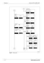
Страница 97: ... 1 Menu tree 1 EXE CLOSE NEW EDIT POSI COPY RENAME PROECT DELETE CHANGE MELFA CR800 D MELFA CR800 D Main menu Start screen 1 File menu Menu to input the file name Menu for program editing Copy program Rename program Delete program Protect program Menu for position editing Refer to separate instruction man ual CR800 R iQ Platform Support ing Extended Function Instruction Manual BFP A3528 for 1 SQ D...

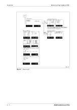
Страница 98: ...1E Fig 6 1 Menu tree 2 CHECK TEST RUN ORIGIN DATA MECH TOOL 2 RUN menu Jog mode 2 Mechanical end stops 3 Calibration device 3 Set parameter 4 Set home position release articulated joint brake Test mode Set home position 1 Data Program selection Operation ...

Страница 99: ... Menu tree FR series 6 3 R002302E Fig 6 1 Menu tree 3 ABS USER BRAKE INITIALIZE POWER ClOCK VERSION 4 ABS method 2 Battery and switch on time 3 Set date time 5 Set Initialize 5 USER menu 2 Release brake 1 Initialize 4 Version display ...

Страница 100: ...es 2 Workpiece coordinates 6 Enhanced Menu Tool Menu Press HAND button for a long period Hand menu HAND key JOG menu JOG key Tool Menu Press HAND button for a long period This function enable direct control of the robot by PLC Refer to separate manual CR800 R iQ Platform Supporting Extended Function Instruction Manual BFP A3528 ...

Страница 101: ... right Change the character by pressing the key repeatedly For instance pressing the ABC key repeatedly allows you to select from the following characters A B C a b c When selecting letters assigned to the same key you can move the cursor along a position by using the arrow key ã The following characters are assigned to the keys key key ñ key _ Exampleå 51 is entered as the program name To do this...

Страница 102: ...ter B of string ABY is to be changed to an M resulting in the new string AMY Move the cursor with the key to the B character and press the following keys CLEAR 1 x MNO 3 x WXYZ R001491E Fig 6 4 Clear a character NOTE Pressing the CLEAR key for a longer period clears all the characters in the brackets NEW PROGRAM PROGRAM NAME CLOSE ABC NEW PROGRAM PROGRAM NAME ABY CLOSE ABC AMY ...

Страница 103: ...e MODE switch of the controller to MANUAL Activate the Teaching Box by setting the ENABLE DISABLE switch of the Teaching Box to ENABLE The start screen appears after switching on After the start screen appears press EXE key to call up the main men R002757E R002759E Top disabled Bottom enabled lights up Teaching Box Rear of the Teaching Box MELFA CR800 D Ver S3 RH 3FH5515 D COPYRIGHT C 2011 MITSUBI...

Страница 104: ...ey The FILE EDIT menu is displayed R001544E R001544E FILE EDIT 1 20 Rem 136320 1 08 04 24 17 20 32 22490 2 08 04 24 14 56 08 694 A1 08 04 24 13 05 54 2208 B1 08 04 24 13 05 54 1851 COPY 123 POSI EDIT NEW MENU 1 FILE EDIT 2 RUN 3 PARAM 4 ORIGIN BRK 5 SET INIT 6 ENHANCED CLOSE 123 FILE EDIT 1 20 Rem 136320 1 08 04 24 17 20 32 22490 2 08 04 24 14 56 08 694 A1 08 04 24 13 05 54 2208 B1 08 04 24 13 05 ...

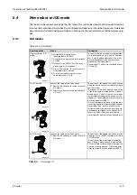
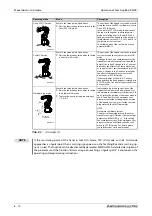
Страница 105: ... listed above l Press the function key to switch to the tool JOG mode l To move the axes press appropriate key X Y Z A B C The position of the tipped tool can be moved along the axes in the tool coordinate system in tool JOG mode The tipped tool is moved linearly The position of the robot can be rotated by keys A B and C around axes X Y and Z of the tool coordinate system without changing the posi...

Страница 106: ...per is rotated as in XYZ JOG mode The axes of robot type RH can be controlled Workpiece jog mode R002737E Execute the three points listed above l Press the function key three times to switch to workpiece JOG mode l To move the axes press appropriate key X Y Z A B C In workpiece jog mode the position of the tipped tool can be moved along the axles of the workpiece coordinate system Buttons A B and ...

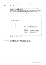
Страница 107: ... is affected and it is not possible for the user to remedy the cause of the error fault then you must immediately contact your MITSUBISHI ELECTRIC sales agent P DANGER Operationmustbestoppedimmediatelyifyouobserveslightdeviationswhenoperatingthe robot or the auxiliary equipment If immediate shutdown would result in concomitant dan gers and hazards then you must select a suitable time If the robot ...

Страница 108: ...numbers the errors causes and the countermeasures are listed in the operating and pro gramming instructions If an error can not be remedied by the countermeasures listed then please contact your sales partner Fig 7 1 Design of an error message NOTE The last position of the error number may be an axis number Example Error number H0931 means overcurrent of axis J1 motor ã 0 0 0 0 An error marked wit...

Страница 109: ...error message contains information on which fuse has to be replaced 7 4 1 Fuse and error messages 7 4 2 Fuse of power supply of pneumatic gripper hand If you see error message H0083 replace fuse rated current 1 6 A Error code Description Fuse H0083 Fuse of power supply or pneumatic gripper hand defec tive F3 rated current 1 6 A type LM16 Tab 7 1 Fuses R002738E Fig 7 2 Hand fuse exchange place Fron...

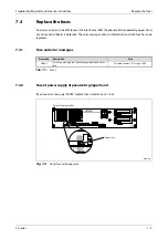
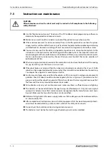
Страница 110: ...ated arm robot or the J3 axis SCARA robot must be supported manually to ensure that they do not fall uncontrolled into the end stop You require the support of a second person for this Small amounts of grease may exit from the robot arm If this can result in soiling or environmental pollution then the robot should be checked regularly for loss of grease If you determine that grease is exiting at th...

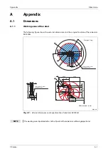
Страница 111: ...rnal dimensions and range of motion of robot arm RV 2FR B NOTE The working area stipulated refers to the P point of the robot arm without gripper hand R 1 3 9 5 240 240 R505 185 80 75 100 P 160 80 80 623 5 85 140 120 389 6 1 2 0 799 6 94 6 230 50 504 6 70 504 6 504 6 R504 6 R139 5 270 295 64 P R 300 Weight 19 kg Solenoid valve option Installation space Solenoid valve option Installation space All ...

Страница 112: ...f motion of robot arm RV 2FRL B NOTE The working area stipulated refers to the P point of the robot arm without gripper hand 160 80 80 944 649 R649 R 1 6 2 199 240 240 295 310 50 11 649 120 1 1 7 R162 R649 70 335 649 494 5 85 140 80 75 703 100 185 64 P R P 300 Weight 21 kg Solenoid valve option Installation space Solenoid valve option Installation space All dimensions in mm ...

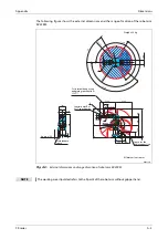
Страница 113: ...pulated refers to the P point of the robot arm without gripper hand 240 240 R 1 3 5 8 R 5 1 4 5 140 114 R 1 3 1 166 6 0 P R136 8 R514 5 397 514 5 47 864 5 514 5 514 5 85 125 350 275 235 50 241 170 690 15 115 126 1 1 3 183 250 120 1 1 2 0 1 2 0 76 66 R 300 P Weight 39 kg All dimensions in mm For internal hand wiring andpipingspecifications SH Control point R of SH specification Maintenance space Ap...

Страница 114: ...ed refers to the P point of the robot arm without gripper hand 240 240 R 6 4 8 7 3 5 3 5 114 R 1 3 1 R 1 4 0 4 166 P R140 4 R648 7 490 648 7 648 7 648 7 140 998 7 85 125 310 350 50 335 1 2 0 120 183 250 241 170 764 9 15 115 126 120 76 66 1 1 4 1 R P 300 Weight 41 kg All dimensions in mm For internal hand wiring andpipingspecifications SH Maintenance space Approx 100 Control point R of SH specifica...

Страница 115: ...tipulated refers to the P point of the robot arm without gripper hand 240 240 R 713 4 R 197 4 R 1 5 9 114 166 66 P 713 4 713 4 1113 4 713 4 568 4 R197 4 R713 4 168 4 400 340 50 370 85 125 1 1 5 1 2 5 207 6 250 120 76 66 200 278 844 4 15 9 135 143 R P 324 Weight 65 kg All dimensions in mm For internal hand wiring andpipingspecifications SH Maintenance space Approx 100 Control point R of SH specific...

Страница 116: ...ted refers to the P point of the robot arm without gripper hand 240 240 R 9 0 7 7 R 1 9 2 8 145 215 145 215 166 P 278 200 939 4 15 9 143 135 752 3 352 3 R192 8 R907 7 1307 7 400 435 50 470 85 125 907 7 907 7 907 7 102 1 1 0 1 3 0 207 6 250 1 2 0 R P 324 Weight 67 kg All dimensions in mm For internal hand wiring andpipingspecifications SH Maintenance space Approx 100 Control point R of SH specifica...

Страница 117: ...pulated refers to the P point of the robot arm without gripper hand 185 114 R277 6 R277 6 190 190 R 1 5 0 2 6 R 5 2 9 R 5 2 9 P R 5 1 7 3 1 9 6 9 2 1 399 1 5 0 1821 5 973 7 9 0 R399 846 9 157 5 1242 6 R1372 6 130 1 3 0 529 85 805 1152 65 565 450 242 5 160 300 347 300 125 66 130 250 P 324 Weight 130 kg For internal hand wiring andpipingspecifications SH Control point R of SH specification All dimen...

Страница 118: ...area stipulated refers to the P point of the robot arm without gripper hand 450 410 65 242 5 997 250 130 430 300 347 160 300 683 6 1 5 0 280 3 1413 8 458 9 157 5 550 P 97 130 833 8 R280 3 R R963 8 90 1 3 0 150 166 185 R 1 0 9 3 8 190 190 R410 3 R 2 7 7 6 P 908 9 963 8 Weight 120 kg For internal hand wiring andpipingspecifications SH Control point R of SH specification All dimensions in mm Space fo...

Страница 119: ...ng area stipulated refers to the P point of the robot arm without gripper hand P R 1182 4 1258 1 9 0 157 5 732 4 1708 1 930 5 1 5 0 R1258 1 R327 6 130 327 6 1128 1 1 3 0 1152 65 565 450 347 160 300 242 5 690 97 430 150 300 130 12 P R457 6 R 1 3 8 7 9 190 190 166 R277 6 185 250 Weight 130 kg For internal hand wiring andpipingspecifications SH Control point R of SH specification All dimensions in mm...

Страница 120: ... area stipulated refers to the P point of the robot arm without gripper hand 450 410 65 242 5 997 250 130 430 300 347 160 300 683 6 1 5 0 280 3 1413 8 458 9 157 5 550 P 97 130 833 8 R280 3 R R963 8 90 1 3 0 150 166 185 R 1 0 9 3 8 190 190 R410 3 R 2 7 7 6 P 908 9 963 8 Weight 120 kg For internal hand wiring andpipingspecifications SH Control point R of SH specification All dimensions in mm Space f...

Страница 121: ...ies A 11 The following figure shows the external dimensions and the range of motion of the robot arm RH 1FRHR5515 R002746E Fig A 11 External dimensions and range of motion of robot arm RH 1FRHR Weight 49 kg All dimensions in mm ...

Страница 122: ... of robot arm RH 3FRHR3515 12 175 175 180 195 420 115 360 340 180 160 135 124 112 135 112 Rz25 Rz25 90 225 225 225 225 R 1 7 5 80 53 336 310 R 2 5 2 5 230 300 500 R 3 5 0 246 A 170 A B Weight 24 kg All dimensions in mm No 1 arm rotation radius Installation surface Robot origin 2 M12 suspension hole 4 M8 jack up hole 4 Ø9 installation hole Installation reference Installation reference Robot A B RH ...

Страница 123: ... 10 40 357 10 26 10 J 82 188 65 55 130 225 A 145 E G 170 F D B C Y All dimensions in mm Only Clean spec Robot A B C D E F G H J Weight RH 3FRH3515 125 R350 R142 210 R253 220 R174 342 150 29 kg RH 3FRH3512C 125 R350 R142 224 R253 268 R196 342 120 29 kg RH 3FRH4515 225 R450 R135 210 R253 220 R174 337 150 29 kg RH 3FRH4512C 225 R450 R135 224 R253 268 R197 337 120 29 kg RH 3FRH5515 325 R550 R191 160 R...

Страница 124: ...174 342 340 7 938 526 36 kg RH 6FRH3534M C 125 R350 R142 224 R253 268 R196 342 340 43 938 526 36 kg RH 6FRH4520 225 R450 R135 210 R253 220 R174 337 200 133 798 386 36 kg RH 6FRH4520M C 225 R450 R135 224 R253 268 R197 337 200 133 798 386 36 kg RH 6FRH4534 225 R450 R135 210 R253 220 R174 337 340 7 938 526 36 kg RH 6FRH4534M C 225 R450 R135 224 R253 268 R197 337 340 43 938 526 36 kg RH 6FRH5520 325 R...

Страница 125: ...0 1080 1180 350 450 R295 65 kg RH 12FRH55xxM C 225 325 R550 R191 145 320 1080 1180 350 450 R382 65 kg RH 12FRH70xx 375 325 R700 R216 145 240 1080 1180 350 450 R295 67 kg RH 12FRH70xxM C 375 325 R700 R216 145 320 1080 1180 350 450 R382 67 kg RH 12FRH85xx 525 325 R850 R278 153 1080 1180 350 450 69 kg RH 12FRH85xxM C 525 325 R850 R278 153 240 1080 1180 350 450 R367 69 kg RH 20FRH85xx 525 325 R850 R27...

Страница 126: ...pendix A 16 A 1 2 Dimensions of the controller and the CPU CR800 controller R002748E Fig A 16 Dimensions of the CR800 controller 430 30 30 3 5 370 99 5 96 425 340 45 40 45 All dimensions in mm Weight approx 12 5 kg ...

Страница 127: ...Appendix Dimensions FR series A 17 Robot CPU R16RTCPU R002749E Fig A 17 Dimensions of robot CPU R16RTCPU All dimensions in mm Weight 0 33 kg ...

Страница 128: ...Dimensions Appendix A 18 ...

Страница 129: ...roller 4 9 robot arm 3 31 robot system 3 30 I Installation 3 1 J JOG modes 6 9 M Mains connection 4 9 Maintenance instructions 7 4 Menu tree 6 1 Model name 1 2 Move robot 6 9 O Overview Controllers 1 1 Robot models 1 1 Overview of models 1 1 R Remedy fault 7 1 Replace fuse 7 3 Robot arm Components 2 5 Overview of models 1 1 Set up 3 16 S Safety diagnosis function 4 13 SCARA robot 2 6 Scope of deli...

Страница 130: ...A 20 Index Appendix ...

Страница 131: ......

Страница 132: ......

Страница 133: ......

Страница 134: ......

Страница 135: ......

Страница 136: ......

Страница 137: ......

Страница 138: ......

Страница 139: ......

Страница 140: ......

Страница 141: ......

Страница 142: ......

Страница 143: ......

Страница 144: ......

Страница 145: ......

Страница 146: ......

Страница 147: ......

Страница 148: ......

Страница 149: ......

Страница 150: ......

Страница 151: ......

Страница 152: ......

Страница 153: ......

Страница 154: ......

Страница 155: ......

Страница 156: ......

Страница 157: ......

Страница 158: ......

Страница 159: ......

Страница 160: ......

Страница 161: ......

Страница 162: ......

Страница 163: ......

Страница 164: ......

Страница 165: ......

Страница 166: ...KON BELARUS Prospect Nezavisimosti 177 9 BY 220125 Minsk Phone 375 0 17 393 1177 Fax 375 0 17 393 0081 INEA RBT d o o BOSNIA AND HERZEGOVINA Stegne 11 SI 1000 Ljubljana Phone 386 0 1 513 8116 Fax 386 0 1 513 8170 AKHNATON BULGARIA 4 Andrei Ljapchev Blvd PO Box 21 BG 1756 Sofia Phone 359 0 2 817 6000 Fax 359 0 2 97 44 06 1 INEA CR CROATIA Losinjska 4 a HR 10000 Zagreb Phone 385 0 1 36 940 01 02 03 ...

Отзывы: