


37. CONNECTION TO JTEKT PLC
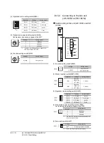
37.3 Connection Diagram
37 - 7
36
CONNECTION T
O
KO
YO EI
P
L
C
37
CONNECTION T
O
JT
EKT PLC
38
CONNECTION T
O
SHA
R
P P
LC
39
CONN
ECT
ION T
O
SHIN
KO
TE
CHNOS
INDI
CA
TI
NG
CONT
ROL
LER
40
CON
N
E
C
T
ION T
O
CHINO CON
T
ROLLER
41
CONNECTION
T
O
T
O
SHI
BA PLC
42
C
O
NNECTION T
O
T
O
SHI
BA MACHI
NE
PLC
43
CONNECTION T
O
P
A
NASO
NIC SER
V
O
AMPLI
F
IE
R
RS422 connection diagram 3)
*1
Terminating resistors should not be provided for a PLC and an RS-
232/RS-422 interface converter which will be terminals.
*2
Connect FG grounding to the appropriate part of a cable shield line.
RS422 connection diagram 4)
*1
Terminating resistors should not be provided for a PLC and an RS-
232/RS-422 interface converter which will be terminals.
*2
Connect FG grounding to the appropriate part of a cable shield line.
RS422 connection diagram 5)
*1
Terminating resistors should not be provided for a PLC and an RS-
232/RS-422 interface converter which will be terminals.
*2
Connect FG grounding to the appropriate part of a cable shield line.
RS422 connection diagram 6)
*1
Terminating resistors should not be provided for a PLC and an RS-
232/RS-422 interface converter which will be terminals.
*2
Connect FG grounding to the appropriate part of a cable shield line.
RS422 connection diagram 7)
*1
Terminating resistors should not be provided for a PLC and an RS-
232/RS-422 interface converter which will be terminals.
*2
Set the terminating resistor setting switch of the GOT main unit to
"Disable".
*3
Connect FG grounding to the appropriate part of a cable shield line.
Precautions when preparing a cable
(1) Cable length
(a) The length of the RS-422 cable used for
connecting the connected equipment to the
communication converter
The length of the RS-422 cable must be 500m or
less.
(b) The length of the RS-422 cable used for
connecting the connected equipment to the GOT.
The total distance (between GOT and controllers)
of RS-422 cable must be 13m or less.
(2) Connector conversion box side connector
For the Connector conversion box side connector, refer
to the following.
(3) JTEKT PLC side connector
Use the connector compatible with the JTEKT PLC side
module.
For details, refer to the JTEKT PLC user's manual.
Connecting terminating resistors
(1) GOT side
When connecting a JTEKT PLC to the GOT, a
terminating resistor must be connected to the GOT.
Set the terminating resistor setting switch of the GOT
main unit to "Disable".
For the procedure to set the terminating resistor, refer
to the following.
RD(+)
RD(-)
TD(+)
TD(-)
0V
FG
S+
S-
R+
R-
0V
FG
S+
S-
R+
R-
0V
FG
*2
*2
RS-232/RS-422
interface converter
*1
Link unit side
*1
Link unit side
*1
S+
S-
R+
R-
0V
FG
S+
S-
R+
R-
0V
FG
*2
*2
S+
S-
R+
R-
0V
FG
Link unit
side
*1
Link unit
side
*1
Link unit
side
*1
RD(+)
RD(-)
TD(+)
TD(-)
0V
FG
L1S+
L1S-
L1R+
L1R-
0V
FG
L1S+
L1S-
L1R+
L1R-
0V
FG
*2
*2
RS-232/RS-422
interface converter
*1
PLC side
*1
PLC side
*1
L1S+
L1S-
L1R+
L1R-
0V
FG
L1S+
L1S-
L1R+
L1R-
0V
FG
L1S+
L1S-
L1R+
L1R-
0V
FG
*2
*2
PLC side
*1
PLC side
*1
PLC side
*1
L1S+
L1S-
L1R+
L1R-
0V
FG
S+
S-
R+
R-
0V
FG
PLC
side
*1
Link unit
side
*1
2
7
1
6
5
3
4
8
9
-
RDA
RDB
SDA
SDB
SG
RSA
CSA
RSB
CSB
FG
*3
Connector conversion
box
side
*2
Содержание GT16
Страница 1: ......
Страница 2: ......
Страница 46: ...1 4 1 OVERVIEW 1 1 Features ...
Страница 54: ...2 8 2 SYSTEM CONFIGURATION 2 2 System Equipment ...
Страница 60: ...3 6 3 SPECIFICATIONS 3 4 Battery specifications ...
Страница 72: ...5 8 5 UL cUL STANDARDS AND EMC DIRECTIVE 5 2 EMC Directive ...
Страница 102: ...6 30 6 OPTION 6 7 Connector Conversion Box ...
Страница 106: ...7 4 7 INSTALLATION 7 1 Installing Procedure ...
Страница 110: ...8 4 8 COMMUNICATION CABLE 8 1 Overview of Communication Cable ...
Страница 130: ...9 20 9 HANDLING OF POWER WIRING AND SWITCH 9 4 Switch Wiring ...
Страница 142: ...10 12 10 UTILITY FUNCTION 10 3 Utility Display ...
Страница 184: ...11 42 11 DISPLAY AND OPERATION SETTINGS GOT SET UP 11 4 Maintenance Function ...
Страница 202: ...12 18 12 COMMUNICATION INTERFACE SETTING COMMUNICATION SETTING 12 3 Ethernet Setting ...
Страница 226: ...13 24 13 DEBUG 13 3 Memory Data Control ...
Страница 248: ...14 22 14 SELF CHECK 14 2 Batch Self Check ...
Страница 350: ...15 102 15 DATA CONTROL 15 3 OS Project Information ...
Страница 410: ...19 22 19 TROUBLESHOOTING 19 2 Error Message and System Alarm ...
Страница 418: ...App 8 APPENDICES Appendix 3 Transportation Precautions ...
Страница 422: ...REVISIONS 4 ...
Страница 425: ......
Страница 426: ......
Страница 427: ......
Страница 428: ......
Страница 470: ......
Страница 510: ...21 22 21 COMPUTER LINK CONNECTION 21 6 Precautions ...
Страница 568: ...22 58 22 ETHERNET CONNECTION 22 5 Precautions ...
Страница 584: ......
Страница 626: ...25 14 25 SERVO AMPLIFIER CONNECTION 25 7 Precautions ...
Страница 632: ...26 6 26 ROBOT CONTROLLER CONNECTION 26 6 Precautions ...
Страница 647: ...MULTIPLE GOT CONNECTIONS 29 GOT MULTI DROP CONNECTION 29 1 ...
Страница 648: ......
Страница 659: ...MULTI CHANNEL FUNCTION 30 MULTI CHANNEL FUNCTION 30 1 ...
Страница 660: ......
Страница 675: ...FA TRANSPARENT FUNCTION 31 FA TRANSPARENT FUNCTION 31 1 ...
Страница 676: ......
Страница 742: ...31 66 31 FA TRANSPARENT FUNCTION 31 7 Precautions ...
Страница 744: ......
Страница 766: ...32 22 32 CONNECTION TO IAI ROBOT CONTROLLER 32 7 Precautions ...
Страница 802: ...34 10 34 CONNECTION TO OMRON TEMPERATURE CONTROLLER 34 7 Precautions ...
Страница 834: ...36 18 36 CONNECTION TO KOYO EI PLC 36 6 Device Range that Can Be Set ...
Страница 858: ...38 12 38 CONNECTION TO SHARP PLC 38 6 Device Range that Can Be Set ...
Страница 868: ...39 10 39 CONNECTION TO SHINKO TECHNOS INDICATING CONTROLLER 39 7 Precautions ...
Страница 902: ...42 6 42 CONNECTION TO TOSHIBA MACHINE PLC 42 6 Device Range that Can Be Set ...
Страница 908: ...43 6 43 CONNECTION TO PANASONIC SERVO AMPLIFIER 43 7 Precautions ...
Страница 970: ...48 12 48 CONNECTION TO FUJI TEMPERATURE CONTROLLER 48 7 Precautions ...
Страница 1052: ...52 26 52 CONNECTION TO AZBIL CONTROL EQUIPMENT 52 7 Precautions ...
Страница 1102: ...55 14 55 CONNECTION TO GE PLC 55 7 Precautions ...
Страница 1114: ...57 4 57 CONNECTION TO SICK SAFETY CONTROLLER 57 5 Device Range that Can Be Set ...
Страница 1128: ...59 2 59 CONNECTION TO HIRATA CORPORATION HNC CONTROLLER ...
Страница 1130: ...60 2 60 CONNECTION TO MURATEC CONTROLLER ...
Страница 1131: ...MICROCOMPUTER CONNECTION 61 MICROCOMPUTER CONNECTION SERIAL 61 1 62 MICROCOMPUTER CONNECTION ETHERNET 62 1 ...
Страница 1132: ......
Страница 1270: ...62 68 62 MICROCOMPUTER CONNECTION ETHERNET 62 8 Precautions ...
Страница 1271: ...MODBUS CONNECTIONS 63 MODBUS R RTU CONNECTION 63 1 64 MODBUS R TCP CONNECTION 64 1 ...
Страница 1272: ......
Страница 1292: ...64 12 64 MODBUS R TCP CONNECTION 64 7 Precautions ...
Страница 1293: ...CONNECTIONS TO PERIPHERAL EQUIPMENT 65 VNC R SERVER CONNECTION 65 1 ...
Страница 1294: ......
Страница 1298: ...65 4 65 VNC R SERVER CONNECTION 65 4 Setting in Personal Computer ...
Страница 1302: ...REVISIONS 4 ...
Страница 1305: ......
Страница 1306: ......