


5. UL, cUL STANDARDS AND EMC DIRECTIVE
5.2 EMC Directive
5 - 3
1
OV
ER
VI
EW
2
SY
STEM
CONFIGURA
TION
3
SP
ECI
F
IC
A
T
IO
NS
4
PA
R
T
S
N
A
M
E
5
UL, c
U
L
S
TANDARDS
A
N
D
E
MC
DIRECTIVE
6
OP
TIO
N
7
INST
ALL
A
TI
ON
8
COMMUNICA
TION
CABLE
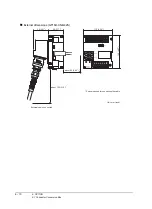
Control panel
Make sure to combine the GT16 Handy GOT with the Connector Conversion Box to comply with the EMC directive.
The Connector conversion box is an open type device (device installed to another device) and must be installed in a
conductive control panel.
It not only assure the safety but also has a large effect to shut down the noise generated from GOT, on the control
panel.
(1) Control panel
(a) The control panel must be conductive.
(b) When fixing a top or bottom plate of the control panel with bolts, do not coat the plate and bolt surfaces so
that they will come into contact.
And connect the door and box using a thick grounding cable in order to ensure the low impedance under
high frequency.
(c) When using an inner plate to ensure electric conductivity with the control panel, do not coat the fixing bolt
area of the inner plate and control panel to ensure conductivity in the largest area as possible.
(d) Ground the control panel using a thick grounding cable in order to ensure the low impedance under high
frequency.
(2) Connection of power and ground wires
Ground and power supply wires for the GOT must be connected as described below.
Provide a grounding point near the GOT. Short-circuit the FG terminals of the GOT (FG: frame ground) and
ground them with the thickest and shortest wire possible (The wire length must be 30cm (11.81in.) or shorter.)
The FG terminals function is to pass the noise generated in the PC system to the ground, so an impedance that
is as low as possible must be ensured. As the wires are used to relieve the noise, the wire itself carries a large
noise content and thus short wiring means that the wire is prevented from acting as an antenna.
Note) A long conductor will become a more efficient antenna at high frequency.
(3) Shock protection
In order to prevent those who are unfamiliar with power facility, e.g., an operator, from getting a shock, make
sure to take the following measures on the control panel.
(a) Store the GOT within the control panel locked, and allow only those who are familiar with power facility to
unlock the panel.
(b) Build the structure in order that the power supply will be shut off when the control panel is opened.
(4) Dustproof and waterproof features
The control panel also provides protection from dust, water and other substances. Insufficient ingression
protection may lower the insulation withstand voltage, resulting in insulation destruction. The insulation in the
GOT is designed to cope with the pollution level 2, so use in an environment with pollustion level 2 or better.
Grounding
The following are applicable ground terminals. Use them in the grounded state.
Be sure to ground the GOT for ensuring the safety and complying with the EMC Directive.
Pollution level1 :
An environment where the air is dry and conductive dust does not exist.
Pollution level2 :
An environment where conductive dust does not usually exist, but occasional
temporary conductivity occurs due to the accumulated dust.
Generally, this is the level for inside the control panel equivalent a control room or
on the floor of a typical factory.
Pollution level3 :
An environment where conductive dust exits and conductivity may be generated
due to the accumulated dust.
An environment for a typical factory floor.
Pollution level4 :
Continuous conductivity may occur due to rain, snow, etc. An outdoor environment.
Protective grounding
:
Ensures the safety of the GOT and improves the noise resistance.
Functional grounding
:
Improves the noise resistance.
Содержание GT16
Страница 1: ......
Страница 2: ......
Страница 46: ...1 4 1 OVERVIEW 1 1 Features ...
Страница 54: ...2 8 2 SYSTEM CONFIGURATION 2 2 System Equipment ...
Страница 60: ...3 6 3 SPECIFICATIONS 3 4 Battery specifications ...
Страница 72: ...5 8 5 UL cUL STANDARDS AND EMC DIRECTIVE 5 2 EMC Directive ...
Страница 102: ...6 30 6 OPTION 6 7 Connector Conversion Box ...
Страница 106: ...7 4 7 INSTALLATION 7 1 Installing Procedure ...
Страница 110: ...8 4 8 COMMUNICATION CABLE 8 1 Overview of Communication Cable ...
Страница 130: ...9 20 9 HANDLING OF POWER WIRING AND SWITCH 9 4 Switch Wiring ...
Страница 142: ...10 12 10 UTILITY FUNCTION 10 3 Utility Display ...
Страница 184: ...11 42 11 DISPLAY AND OPERATION SETTINGS GOT SET UP 11 4 Maintenance Function ...
Страница 202: ...12 18 12 COMMUNICATION INTERFACE SETTING COMMUNICATION SETTING 12 3 Ethernet Setting ...
Страница 226: ...13 24 13 DEBUG 13 3 Memory Data Control ...
Страница 248: ...14 22 14 SELF CHECK 14 2 Batch Self Check ...
Страница 350: ...15 102 15 DATA CONTROL 15 3 OS Project Information ...
Страница 410: ...19 22 19 TROUBLESHOOTING 19 2 Error Message and System Alarm ...
Страница 418: ...App 8 APPENDICES Appendix 3 Transportation Precautions ...
Страница 422: ...REVISIONS 4 ...
Страница 425: ......
Страница 426: ......
Страница 427: ......
Страница 428: ......
Страница 470: ......
Страница 510: ...21 22 21 COMPUTER LINK CONNECTION 21 6 Precautions ...
Страница 568: ...22 58 22 ETHERNET CONNECTION 22 5 Precautions ...
Страница 584: ......
Страница 626: ...25 14 25 SERVO AMPLIFIER CONNECTION 25 7 Precautions ...
Страница 632: ...26 6 26 ROBOT CONTROLLER CONNECTION 26 6 Precautions ...
Страница 647: ...MULTIPLE GOT CONNECTIONS 29 GOT MULTI DROP CONNECTION 29 1 ...
Страница 648: ......
Страница 659: ...MULTI CHANNEL FUNCTION 30 MULTI CHANNEL FUNCTION 30 1 ...
Страница 660: ......
Страница 675: ...FA TRANSPARENT FUNCTION 31 FA TRANSPARENT FUNCTION 31 1 ...
Страница 676: ......
Страница 742: ...31 66 31 FA TRANSPARENT FUNCTION 31 7 Precautions ...
Страница 744: ......
Страница 766: ...32 22 32 CONNECTION TO IAI ROBOT CONTROLLER 32 7 Precautions ...
Страница 802: ...34 10 34 CONNECTION TO OMRON TEMPERATURE CONTROLLER 34 7 Precautions ...
Страница 834: ...36 18 36 CONNECTION TO KOYO EI PLC 36 6 Device Range that Can Be Set ...
Страница 858: ...38 12 38 CONNECTION TO SHARP PLC 38 6 Device Range that Can Be Set ...
Страница 868: ...39 10 39 CONNECTION TO SHINKO TECHNOS INDICATING CONTROLLER 39 7 Precautions ...
Страница 902: ...42 6 42 CONNECTION TO TOSHIBA MACHINE PLC 42 6 Device Range that Can Be Set ...
Страница 908: ...43 6 43 CONNECTION TO PANASONIC SERVO AMPLIFIER 43 7 Precautions ...
Страница 970: ...48 12 48 CONNECTION TO FUJI TEMPERATURE CONTROLLER 48 7 Precautions ...
Страница 1052: ...52 26 52 CONNECTION TO AZBIL CONTROL EQUIPMENT 52 7 Precautions ...
Страница 1102: ...55 14 55 CONNECTION TO GE PLC 55 7 Precautions ...
Страница 1114: ...57 4 57 CONNECTION TO SICK SAFETY CONTROLLER 57 5 Device Range that Can Be Set ...
Страница 1128: ...59 2 59 CONNECTION TO HIRATA CORPORATION HNC CONTROLLER ...
Страница 1130: ...60 2 60 CONNECTION TO MURATEC CONTROLLER ...
Страница 1131: ...MICROCOMPUTER CONNECTION 61 MICROCOMPUTER CONNECTION SERIAL 61 1 62 MICROCOMPUTER CONNECTION ETHERNET 62 1 ...
Страница 1132: ......
Страница 1270: ...62 68 62 MICROCOMPUTER CONNECTION ETHERNET 62 8 Precautions ...
Страница 1271: ...MODBUS CONNECTIONS 63 MODBUS R RTU CONNECTION 63 1 64 MODBUS R TCP CONNECTION 64 1 ...
Страница 1272: ......
Страница 1292: ...64 12 64 MODBUS R TCP CONNECTION 64 7 Precautions ...
Страница 1293: ...CONNECTIONS TO PERIPHERAL EQUIPMENT 65 VNC R SERVER CONNECTION 65 1 ...
Страница 1294: ......
Страница 1298: ...65 4 65 VNC R SERVER CONNECTION 65 4 Setting in Personal Computer ...
Страница 1302: ...REVISIONS 4 ...
Страница 1305: ......
Страница 1306: ......