23. FA TRANSPARENT FUNCTION
23.6 Personal Computer Side Setting
23 - 53
17
ROBOT
CONT
ROLLER
CONN
E
C
TION
18
C
NC CONNECTION
19
ENER
GY M
EAS
URIN
G
UNIT/EL
EC
TRIC M
U
LT
I-
ME
ASUR
ING IN
STRU
MEN
T
CO
NNE
CTION
20
GOT
MUL
T
I-DROP
CONNECTION
21
MUL
TI
PL
E-GT1
4, G
T12,
GT
11
, GT
10
CO
NNECTIO
N FUNCTION
22
MUL
T
I-CHA
N
N
E
L
FUNCT
ION
23
F
A
TRANS
P
ARENT
FUNCTION
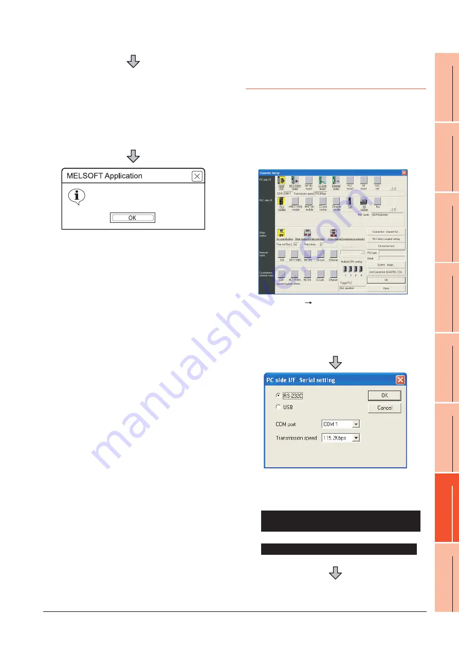
23.6.3 Accessing the PLC by the GX
Developer, PX Developer, GX
Configurator
The setting method for the FA transparent function of GX
Developer is used as an example.
GX Configurator is an add-on software of GX Developer.
(Except for GX Configurator-QP)
Connecting the GOT and PLC in bus
connection or direct CPU connection
(when connecting to QCPU (Q mode))
8.
Specify the number for [Network No.] and [Station
No.] same as the number assigned to the Ethernet
module.
9.
Specify the IP address for [IP Address] same as the
IP address assigned to the built-in Ethernet port
QCPU or Ethernet module.
10.
The screen returns to the [Connection Channel
Setup]. Click [Connection Test] to check if GX Works3
has been connected to the R12CCPU-V.
Successfully connected with the R12CCPU-V
1.
Click [Online]
[Transfer Setup] in GX Developer.
2.
The [Transfer Setup] is displayed.
3.
Set the [Transfer Setup]:
PC side I/F
: Serial USB (COM)
PLC side I/F
: PLC module
Other station
: No specification
4.
Double-click [Serial] of the PC side I/F to display [PC
side I/F Serial setting].
5.
Check-mark either of the following in [PC side I/F
Serial setting].
Mark the [RS-232C] checkbox.
Mark the [USB] checkbox.
When connecting the GOT to PC via modem
When connecting the GOT and PC with serial
When connecting the GOT and PC with USB
Содержание GT15
Страница 2: ......
Страница 34: ...A 32 ...
Страница 92: ......
Страница 110: ...2 18 2 DEVICE RANGE THAT CAN BE SET 2 9 MELSEC WS ...
Страница 134: ...3 24 3 ACCESS RANGE FOR MONITORING 3 7 Connection to the Head Module of CC Link IE Field Network System ...
Страница 186: ...5 10 5 BUS CONNECTION 5 2 System Configuration ...
Страница 218: ...5 42 5 BUS CONNECTION 5 4 Precautions ...
Страница 254: ...6 36 6 DIRECT CONNECTION TO CPU 6 6 Precautions ...
Страница 286: ...7 32 7 COMPUTER LINK CONNECTION 7 6 Precautions ...
Страница 350: ...8 64 8 ETHERNET CONNECTION 8 5 Precautions ...
Страница 368: ...9 18 9 MELSECNET H CONNECTION PLC TO PLC NETWORK 9 5 Precautions ...
Страница 420: ...11 26 11 CC Link IE CONTROLLER NETWORK CONNECTION 11 5 Precautions ...
Страница 440: ...12 20 12 CC Link IE FIELD NETWORK CONNECTION 12 5 Precautions ...
Страница 490: ...13 50 13 CC Link CONNECTION INTELLIGENT DEVICE STATION 13 5 Precautions ...
Страница 510: ......
Страница 564: ...15 54 15 INVERTER CONNECTION 15 7 Precautions ...
Страница 668: ......
Страница 712: ...21 12 21 MULTIPLE GT14 GT12 GT11 GT10 CONNECTION FUNCTION 21 5 Precautions ...
Страница 713: ...MULTI CHANNEL FUNCTION 22 MULTI CHANNEL FUNCTION 22 1 ...
Страница 714: ......
Страница 760: ...22 46 22 MULTI CHANNEL FUNCTION 22 5 Multi channel Function Check Sheet ...
Страница 761: ...FA TRANSPARENT FUNCTION 23 FA TRANSPARENT FUNCTION 23 1 ...
Страница 762: ......
Страница 860: ...REVISIONS 4 ...
Страница 863: ......


