background image

15 - 28

15.3  Resource Data Information

15.3.4

Image file management

■1.

Function of image file management

Deletes, copies, and moves the file created by the hard copy function.
For details of the hard copy function, refer to the following.

 GT Designer3 (GOT2000) Help

■2.

Display operation of image file management

Function

Description

Reference page

Information display of files 
and folders

Displays the kind, name, data size, creation date and time of the file or folder.

15-29
15-30

Delete

Deletes the file.

15-31

Copy

Copies the file.

15-32

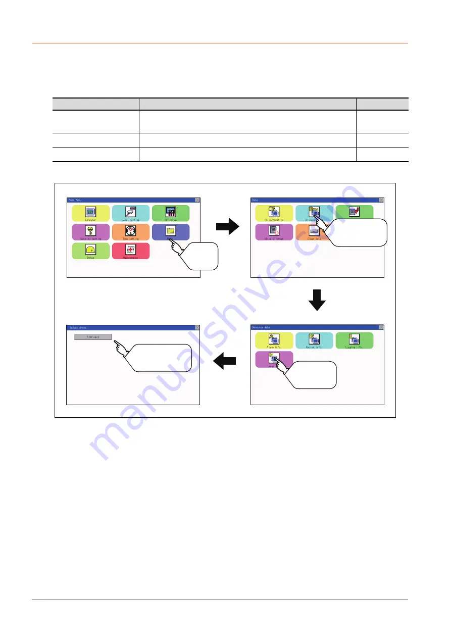
Select a drive and
operate Image data
files

Main Menu

Data

Resource data

Select drive

Touch 
[Data].

Touch 
[Resource Data].

Touch 
[Image file].

Содержание GOT SIMPLE GS2107-WTBD

Страница 1: ...GRAPHIC OPERATION TERMINAL User s Manual GOT SIMPLE Series ...

Страница 2: ......

Страница 3: ...o false output or malfunction Do not use the GOT as the warning device that may cause a serious accident An independent and redundant hardware or mechanical interlock is required to configure the device that displays and outputs serious warning Not doing so can cause an accident due to false output or malfunction When the GOT detects its backlight failure the GOT disables the input operation on th...

Страница 4: ...arately from such wiring and keep them a minimum of 100mm apart Not doing so noise can cause a malfunction Do not press the GOT display section with a pointed material as a pen or driver Doing so can result in a damage or failure of the display section When the GOT is connected to the Ethernet network the available IP address is restricted according to the system configuration When multiple GOTs a...

Страница 5: ...nal power supply used by the system before wiring Failure to do so may result in an electric shock product damage or malfunctions CAUTION Please make sure to ground FG terminal of the GOT power supply section by applying 100Ω or less which is used exclusively for the GOT Not doing so may cause an electric shock or malfunction Correctly wire the GOT power supply section after confirming the rated v...

Страница 6: ...dertightening can cause a short circuit or malfunction Overtightening can cause a short circuit or malfunction due to the damage of the screws or unit CAUTION Do not disassemble or modify the unit Doing so can cause a failure malfunction injury or fire Do not touch the conductive and electronic parts of the unit directly Doing so can cause a unit malfunction or failure The cables connected to the ...

Страница 7: ... updating alarm logging scripts and others are also interrupted Since this interruption makes an impact to the system operation it might cause failure After inhibiting access to the SD card on the GOT utility screen check that the SD card access LED is off and remove the SD card CAUTION If the data storage mounted on the GOT is removed while the GOT is accessed the data storage and files are damag...

Страница 8: ...heck if the unit operates correctly after transportation When fumigants that contain halogen materials such as fluorine chlorine bromine and iodine are used for disinfecting and protecting wooden packaging from insects they cause malfunction when entering our products Please take necessary precautions to ensure that remaining materials from fumigant do not enter our products or treat packaging wit...

Страница 9: ...3 4 2 RS 422 interface 3 4 4 PART NAME 4 1 Front Panel 4 1 4 2 Back Panel 4 2 4 3 Bottom 4 3 5 EMC DIRECTIVE 5 1 Overview 5 1 5 1 1 Conforming standards in the EMC Directive 5 1 5 2 EMC Directive Requirements 5 2 5 2 1 Installing the GOT on the control panel 5 2 5 2 2 Installing a noise filter power supply line filter 5 3 5 2 3 System configuration 5 4 5 2 4 Connection of power cables and ground c...

Страница 10: ...le SD card 8 1 8 1 2 Installation removal procedure of SD card 8 1 9 UTILITY FUNCTION 9 1 Utility Execution 9 1 9 2 Utility Function List 9 2 9 3 Utility Display 9 3 9 3 1 Display operation of main menu 9 5 9 3 2 Utility basic configuration 9 7 9 3 3 Basic operation of settings change 9 8 10 LANGUAGE SETTING LANGUAGE 10 1 Display language setting 10 1 10 1 1 Display language setting function 10 1 ...

Страница 11: ... setting 12 2 12 1 3 Display setting operations 12 3 12 2 Operation Setting Settings for Operation 12 5 12 2 1 Operation setting functions 12 5 12 2 2 Display operation of operation setting 12 6 12 2 3 Setting operation of operation 12 7 12 2 4 Position correction of the touch panel touch panel calibration setting 12 9 12 2 5 Setting the utility call keys 12 11 12 3 Inherent Information 12 13 12 3...

Страница 12: ...ions of SD card access 15 33 15 4 2 Display operation of SD card access 15 33 15 4 3 Operation of SD card access 15 33 15 5 SD Card Format 15 34 15 6 Clear data 15 36 15 6 1 Clear data functions 15 36 15 6 2 Clear data display 15 36 15 6 3 Clear data operation 15 36 15 7 Data Copy 15 37 15 7 1 Display operation of data copy 15 37 15 7 2 Operation of data copy 15 38 15 8 BACKUP RESTORE 15 40 15 8 1...

Страница 13: ... 2 15 Parameter setting 16 35 16 2 16 Keyword 16 37 16 2 17 List monitor 16 39 16 2 18 Action for an incorrect key input 16 40 16 2 19 Error messages and corrective actions 16 41 16 3 FX3U ENET ADP Communication Setting Function 16 42 16 3 1 Specifications 16 42 16 3 2 Display operation of FX3U ENET ADP communication setting function 16 43 16 3 3 Setting operation 16 44 17 MAINTENANCE 17 1 Touch P...

Страница 14: ...ght Shutoff Detection 21 4 21 4 1 Backlight shutoff detection and external alarm 21 4 22 TROUBLESHOOTING 22 1 GOT Restoration Sheets 22 1 23 CONNECTION 24 APPENDIX Appendix 1External Dimensions 24 1 REVISIONS WARRANTY ...

Страница 15: ... Works3 SH 080862ENG 1D7MB2 Manual name Manual number Model code GOT2000 Series Connection Manual Mitsubishi Product For GT Works3 Version1 SH 081197ENG 1D7MJ8 GOT2000 Series Connection Manual Non Mitsubishi Product 1 For GT Works3 Version1 SH 081198ENG 1D7MJ9 GOT2000 Series Connection Manual Non Mitsubishi Product 2 For GT Works3 Version1 SH 081199ENG 1D7MK1 GOT2000 Series Connection Manual Micro...

Страница 16: ...on between a personal computer and a controller via the GOT FA transparent function Obtaining information of Non Mitsubishi products applicable to the GOT GOT2000 Series Connection Manual Non Mitsubishi Product 1 For GT Works3 Version1 GOT2000 Series Connection Manual Non Mitsubishi Product 2 For GT Works3 Version1 Connecting Non Mitsubishi products to the GOT Obtaining information of peripheral d...

Страница 17: ...2310 VTBA GT2310 VTBD GT2308 V GT2308 VTBA GT2308 VTBD GT SoftGOT2000 GT SoftGOT2000 Version1 Abbreviations and generic terms Description SD card L1MEM 2GBSD L1MEM 4GBSD Abbreviations and generic terms Description GT Works3 SW1DNC GTW3 J SW1DND GTW3 J SW1DNC GTW3 E SW1DND GTW3 E SW1DND GTW3 C GT Designer3 Version1 Screen drawing software GT Designer3 for GOT2000 GOT1000 series GT Designer3 Screen ...

Страница 18: ...eries indicates a version CW Configurator C Controller module configuration and monitor tool SW1DND RCCPU E indicates a version MR Configurator2 SW DNC MRC2 E type servo configuration software indicates a version MR Configurator MRZJW SETUP type servo configuration software indicates a version FR Configurator Inverter setup software FR SW SETUP WE indicates a version NC Configurator2 CNC parameter...

Страница 19: ... display Comment display and Numeric display can be arbitrarily arranged on the display Moreover multiple screens created within drawing software can be individually selected or overlapped for the display For details refer to the following GT Designer3 GOT2000 Help 2 Utility Screen The utility screen is a factory drawn horizontal screen that cannot be edited The utility screen can be displayed on ...

Страница 20: ...ition TFT color liquid crystal display Also compatible with digital screen displays with 65536 colors BMP etc High speed monitoring through high speed communication at maximum of 115 2kbps High speed display and high speed touch switch response The operation performance is improved by the analog touch panel 3 More efficient GOT operations including screen design startup adjustment management and m...

Страница 21: ...000 Help Wire for the GOT power supply and the controller 7 WIRING Refer to GOT2000 Series Connection Manual for GT Works3 Version1 Wire for the controller power supply and I O Controller manuals Turn on the power of the GOT and controller Install the OS to the GOT Refer to GT Designer3 GOT2000 Help Check that the OS is installed to the GOT Download project data Refer to GT Designer3 GOT2000 Help ...

Страница 22: ...1 4 1 1 Features ...

Страница 23: ...OT2000 Series Connection Manual For GT Works3 Version1 1 Only hard copy of the screen can be printed 2 2 Component List 1 Explanation of the GOT model name Bar code reader Commercially available Personal computer Commercially available Printer 1 Commercially available SD card GS21 series 0 7 W Panel color type 10 10 07 7 Display color type W 800 480 Resolution D DC24V Power type T TFT color Displa...

Страница 24: ...uter link connection cable GT01 C30R4 25P 3m QnA A motion controller A series For connecting FXCPU D Sub 25 pins connector and GOT For connecting FA CNV CBL and GOT For connecting serial communication unit AJ71QC24 N R4 and GOT GT01 C100R4 25P 10m GT01 C200R4 25P 20m GT01 C300R4 25P 30m Computer link connection cable GT09 C30R4 6C 3m For connecting computer link unit serial communication unit and ...

Страница 25: ...3 Robot programming software MELSOFT RT ToolBox2 mini 5 PC connection cable Sold separately 6 Bar code reader Sold separately 1 Some models with the operations checked by our company are usable For the operation checked models contact your local distributor Product name Model Description GOT screen creation software MELSOFT GT Works3 Version1 SW1DND GTWK3 J Standard license product DVD product SW1...

Страница 26: ...2 4 2 2 Component List ...

Страница 27: ...ion degree 2 only non conductive pollution occurs but temporary conductivity may be produced due to condensation Item Specifications Operating ambient temperature 0 to 50 C Storage ambient temperature 20 to 60 C Operating Storage ambient humidity 10 to 90 RH non condensing The wet bulb temperature is 39 C When the ambient temperature exceeds 40 C maintain the absolute humidity at 40 C and 90 Vibra...

Страница 28: ...ommunicating with controllers Terminating resistor 330Ω fixed RS 232 RS 232 1ch Transmission speed 115200 57600 38400 19200 9600 4800bps Connector shape D sub 9 pins Male Application For communication with controllers and a bar code reader For PC connection Project data read write FA transparent function Ethernet Data Transfer method 100BASE TX 10BASE T 1ch Connector shape RJ 45 modular jack Appli...

Страница 29: ...ments under exposition of oil or chemicals for a long period of time or in environments filled with oil mist 3 3 Power Supply Specifications POINT POINT POINT Operation at momentary power failure The GOT continues to operate even upon 5ms or shorter instantaneous power failure The GOT stops operating if there is extended power failure or voltage drop while it automatically resumes operation as soo...

Страница 30: ... pin arrangement 3 4 2 RS 422 interface The following shows the connector for the RS 422 interface of the GOT For the connection cable connector of the GOT side use a connector and a connector cover which can be connected to the GOT connector 1 Connector model 2 Connector pin arrangement GOT Connector type Connector model Manufacturer GS series D sub 9 pins Male Inch screw type 17LE 23090 27 D3CC ...

Страница 31: ...ME 4 PART NAME 4 1 Front Panel No Name Specifications 1 Display section Displays the utility screen and the user creation screen 2 Touch panel For operating the touch switches in the utility screen and the user creation screen 1 2 ...

Страница 32: ...ost for data transfer and saving 5 Hole for preventing the USB cable from unplugging Hole for preventing the USB cable from unplugging with a banding band 6 Rating plate nameplate Model name current consumption production number hardware version and Boot OS version are described 7 SD card interface Interface for mounting an SD card to the GOT 8 SD card access LED ON SD card is accessed OFF SD card...

Страница 33: ...AME 4 3 Bottom GS2110 WTBD GS2107 WTBD No Name Specifications 1 Hole for unit installation fittings Hole for the inserting installation fittings accessory during the GOT installation to the panel 4 holes at top and bottom 1 1 ...

Страница 34: ...4 4 4 3 Bottom ...

Страница 35: ...ectromagnetic emissions from the product 30 MHz to 230 MHz QP 30 dBμV m measured at 30 m 2 3 230 MHz to 1000 MHz QP 37 dBμV m measured at 30 m 2 3 IEC61000 4 2 Electrostatic immunity 1 Immunity test in which static electricity is applied to the cabinet of the equipment Contact discharge 4 kV Aerial discharge 8 kV IEC61000 4 3 Radiated electromagnetic field amplitude modulation 1 Immunity test in w...

Страница 36: ...ate and the control panel Ground the control panel using a thick grounding cable to ensure the low impedance under high frequency The diameter of cable holes on the control panel must be 10 cm or less If the diameter of the hole is 10 cm or more radio waves may leak To reduce the chance of radio waves leaking out ensure that the space between the control panel and its door is as small as possible ...

Страница 37: ... a noise filter 1 Prohibition of bundling cables Do not bundle the input and output cables of the noise filter Bundling the cables inducts the noise from the output side cable into the input side cable where noise has been eliminated by the noise filter 2 Grounding the noise filter Connect the ground terminal of the noise filter to the control panel with a short cable as much as possible approxima...

Страница 38: ...ions 4 Non Mitsubishi PLC inverter and servo amplifier connections POINT POINT POINT Connected devices When connecting the GOT to a non Mitsubishi PLC refer to the manual about the EMC Directive compliance of the connected device such as a PLC and a microcomputer 5 2 4 Connection of power cables and ground cables Carry out wiring and connect the power and ground cables according to the following i...

Страница 39: ...t interface of the GOT 2 Direct CPU connection 1 RS 232 cable and RS 422 cable Install a ferrite core to the cable in the positions as shown in the figure below 3 Computer link connection 1 RS 232 cable and RS 422 cable Strip off the sheath at both ends of the cable as shown in the figure below to expose braided shield sections for grounding The braided shield sections are used for grounding with ...

Страница 40: ... the equipment must determine the method to comply with the EMC Directive and conformance to the directive 1 RS 422 485 cable When connecting each signal wire except SG and FG wires twist two signal wires as shown below Connect two or more SG wires 2 RS 232 cable Twist each signal wire except SG and FG wires with the SG wire Install a ferrite core to the cable in the positions as shown in the figu...

Страница 41: ... with the cable clamp AD75CK To ground a bus connection cable ground the braided cable for grounding to the control panel by tightening a screw 2 Precautions Do not arrange the cable clamp close to the other cables that are not clamped The noise from the control panel may enter the cable clamp and adversely affect the GOT Braided shield Cable clamps For the attachment details of cable clamps refer...

Страница 42: ...5 8 5 2 EMC Directive Requirements ...

Страница 43: ...in this manual Not doing so can cause an electric shock fire malfunction or product damage or deterioration Never drop cutting chips and electric wire chips into the ventilation window of the GOT when you drill screw holes or perform wiring Otherwise fire failure or malfunction may be caused Connect connection cables securely to the specified connectors while the power is turned OFF Imperfect conn...

Страница 44: ...0 degrees clockwise looking from the display section side is required 1 Vertical Format 50mm 1 97 or more 2 Vertical Format 80mm 3 14 or more Installation Environment A D mm inch B mm inch C mm inch E mm inch In the presence of radiated noise or heat generating equipment nearby 50mm 1 97 or more 80mm 3 14 or more 1 50mm 1 97 or more 2 100mm 3 94 or more In the absence of radiated noise or heat gen...

Страница 45: ...OT will have a longer lifetime if used within the mounting angles shown above Ideally the temperature inside the control panel should not exceed 0 to 40 C 2 Vertical installation When the temperature inside the control panel is 40 to 50 C the mounting angle should be in the range from 60 to 105 degrees The GOT will have a longer lifetime if used within the mounting angles shown above Ideally the t...

Страница 46: ...ttached with the GOT If the packing is loose attach the packing to the GOT securely Step 1 Inserting into the panel face Insert the GOT from the front side of the panel Step 2 Fixing the GOT Engage the hook of the mounting fixture accessory to the unit fixing hole of the GOT and fix them by tightening the mounting screws accessory in the torque range of 0 36 to 0 48N m Step 3 A protection film is ...

Страница 47: ...orrect input from the touch panel In addition undertightening can disable waterproof or oil proof effect Specified torque range 0 36 to 0 48N m 2 Installation panel surface Make sure that the panel surface is free from warpage flaws and irregularities Warpage flaws and irregularities may disable the waterproof effect Select proper panel thickness under consideration of the panel strength For examp...

Страница 48: ...6 6 6 5 Installation Procedure ...

Страница 49: ...ort and thick cable to lower its ground resistance c Ground the power system and the control system separately WIRING PRECAUTIONS WARNING Be sure to shut off all phases of the external power supply used by the system before wiring Failure to do so may result in an electric shock product damage or malfunctions Please make sure to ground FG terminal of the GOT power supply section by applying 100Ω o...

Страница 50: ...ment failures or malfunctions 1 Electrical wire size 2 Wire end processing 1 Connecting the wire directly a Twist the end of the stranded wire Make sure there are no wire whiskers b Do not solder the wire end 2 Using a ferrules with plastic sleeve to connect the wire A wire with a too thick of a wire sheath may not fit the insulation sleeve Refer to the outline drawing for how to select the proper...

Страница 51: ...resistance must be 100W or less If the independent grounding is impossible carry out the shared grounding as shown in fig 2 below Use the cable of 2mm2 or longer for grounding Set the grounding point closer to the GOT to make the grounding cable short as possible Tightening torque for the power terminals 0 5 to 0 6N m Class D grounding Other device GOT Other device GOT Other device GOT 1 Independe...

Страница 52: ...ting the ground cable from the panel that houses control equipment to the panel to which the GOT is grounded When running a single ground cable from the panel that houses such piece of control equipment as a sequencer to the panel to which the GOT is grounded the ground cable may have to be directly connected to the terminal on the GOT If electric potential difference between the ground points cre...

Страница 53: ...hen Remedy 1 is taken Wind the wire around the ferrite core several times approx 3times if a ferrite core is used If the wiring method as shown in Remedy 2 1 is not feasible follow Remedy 2 2 FG Ground cable from the panel that houses control equipment Connection cable Panel grounding Panel grounding Remedy1 1 Use the thickest cable possible FG Connection cable Remedy1 2 Ground cable from the pane...

Страница 54: ...ommunication cable out of the panel make two pullout holes away from each other and pull the cables through Putting both cables through the same pullout hole will increase noise interference Keep the power line and communication cable inside the duct at least 100mm away from each other If that is not possible the use of a metal separator inside the duct can reduce noise interference NFB MC PLC MC ...

Страница 55: ...e ground cable and communication cable away from the load If that is not possible an installation of a surge killer will help reduce noise interference Place the surge killer as close to the load as possible Remedy for AC inductive load Remedy for DC inductive load Output AC C R L Load Keep the ground cable and communication cable away from each other Place the surge killer near the load Output eq...

Страница 56: ...7 8 7 2 Wiring Inside and Outside the Panel ...

Страница 57: ... power supply of the GOT is OFF or Access inhibit is set in the SD card access setting of the GOT 1 Installation Model Specifications L1MEM 2GBSD SD memory card 2GB L1MEM 4GBSD SDHC memory card 4GB NZ1MEM 2GBSD SDHC memory card 2GB NZ1MEM 4GBSD SDHC memory card 4GB NZ1MEM 8GBSD SDHC memory card 8GB NZ1MEM 16GBSD SDHC memory card 16GB Commercially available SD card 1 Step 1 Touch Main Menu Data SD ...

Страница 58: ...support the SD card by hand as it may pop out Failure to do so may cause the SD card to drop from the GOT resulting in a failure or break Step 1 Touch Main Menu Data SD card access Permissions to set Access inhibit 15 4 SD Card Access Check that the SD card access LED turns off When the SD card access LED is off the SD card can be installed or removed even when the GOT is on Step 2 Push the SD car...

Страница 59: ...or installing Boot OS and package data Refer to the following for the installation which uses GT Designer3 GT Designer3 GOT2000 Help For the installation methods of package data with an SD card refer to the following 18 BootOS and System Application Installation Using Data Storage Install directly from GT Designer3 Via a USB interface or Ethernet interface GT Designer3 GT Designer3 Writing package...

Страница 60: ...ting Security level Changing the security level 13 1 Operator Operator management 13 2 Password change Function setting Login Logout 13 3 Time setting Time setting 14 1 Data OS information OS information 15 2 Resource Data Alarm info Deleting or copying alarm log files Converting alarm log files in G1A format CSV TXT format 15 3 1 Recipe info Converting recipe files in G1P format CSV TXT format Co...

Страница 61: ...he main menu will display the setting screen or following selection screen for the item 2 System message switch button This button switches the language used for the utility or system alarms When touching the Language button the Select Language screen is displayed Step 1 Touch the language button of a desired language and touch the OK button to select the language Step 2 Touching the button switch...

Страница 62: ...ges The system message switch button is displayed only for the selectable languages The selectable languages differ depending on the fonts installed in the GOT For the relation between the selectable languages and the fonts refer to the following GT Designer3 GOT2000 Help 3 System language switching using the device The system language can be switched using the system language switching device set...

Страница 63: ...the GOT utility or GT Designer3 For the setting method of the utility call key refer to the following 12 2 5 Setting the utility call keys GT Designer3 GOT2000 Help POINT POINT POINT 1 Prohibited simultaneous 2 point presses Do not touch 2 points or more on the GOT screen simultaneously Touching 2 points or more simultaneously may activate a part other than the touched point 2 Press time of the ut...

Страница 64: ...reen by GT Designer3 For the details of the special function switch refer to the following GT Designer3 GOT2000 Help POINT POINT POINT When limiting the display and operation of the utility When limiting the display and operating users set a password to the GOT using GT Designer3 If a user tries to display the main menu of the utility the password is displayed Refer to the following for the detail...

Страница 65: ...ayed if the Close return button in the right corner of screen is touched returns to the previous screen If this button is touched when directly displayed from monitor screen the screen is closed and returns to monitor screen 3 Scroll button For screens in which the content does not fit on one screen page there is a right or down scroll button on the screen Scroll one line column Scroll window Titl...

Страница 66: ...keyboard on the GOT screen For the keyboard operations refer to the next page c Move to another setting screen Touch the button to move to each setting screen For the setting method of each setting item refer to the setting operation of each setting screen 2 Close Return button Reflect or cancel the changed settings a Close Return button Touching this button closes the screen Depending on the sett...

Страница 67: ...ayed at a position that does not disturb users to input numerical values Step 3 Input numerical value by the keyboard 0 to 9 Key Enter numerical values Enter Key Completes the numerical value input and closes the keyboard Cancel Key Cancels the numerical value input and closes the keyboard Del Key Deletes one character AC Key Deletes all characters key and the keys which are not mentioned do not f...

Страница 68: ...9 10 9 3 Utility Display ...

Страница 69: ...em Description Setting range Language Display language in which the utility functions and dialog windows are displayed can be selected or confirmed in this menu Japanese English Chinese At factory shipment Chinese Step 1 Touch Language to bring up the set up screen Step 2 Select a display language by touching the corresponding button Step 3 After changing the setting touch the button The setting i...

Страница 70: ...y by devices Any device can be used for switching the display language of the utility For details refer to the following GT Designer3 GOT2000 Help When using devices to switch the display language of the utility it does not change even if the display language is switched from the GOT utility screen ...

Страница 71: ...he serial communication port communication 11 4 Ethernet check Checking the Ethernet communication port communication 11 5 Transparent mode Setting the channel No to be used for the communication for the FA transparent function 11 6 Keyword Setting or deleting sequence program protection key words and canceling sequence program protection status for the FXCPU connection 11 7 Function Description C...

Страница 72: ... and other equipment 2 Channel No specification menu BOX Set a channel number to be used by the standard interface 11 1 5 Channel setting operation For the detail of the drivers which can be assigned to each channel refer to this section 3 9 is automatically set to the standard I F 3 USB 0 Set when the communication interface is not used 1 2 Set when connecting to a controller 8 Set when connectin...

Страница 73: ... Driver setting operation The button is displayed in the following case When a channel number other than channel 0 or 9 is set to the standard I F 1 standard I F 2 and standard I F 4 POINT POINT POINT Precautions for communication between GOT and connected devices 1 Installing Communication driver and downloading Communication Settings To perform communication with the connected device the followi...

Страница 74: ...g the ten key depending on the setting 0 to 9 Use these keys to enter numerical values Enter 0 to disable the screen saver function ESC Closes the ten key window without saving any value entered AC Deletes the entire string of numerical characters that are being entered DEL Deletes a digit from a string of numerical characters that are being entered ENT Enters the value for the clock that has been...

Страница 75: ...ameter setting menu depend on the type of communication driver that is installed on the GOT in use Refer to the section below for the setting contents of various drivers GT Designer3 GOT2000 Help Step 4 Touch the button to display the window confirming whether to save the settings Step 5 Touch the YES button to save the settings and restart Touch the NO button to discard the changes ...

Страница 76: ...river display box of a communication parameter to be set Step 2 The screen is switched to the communication detail setting Set the communication parameter on this screen GOT IP address setting 11 2 GOT IP Address Setting Step 3 When the button is touched it returns to the previous screen Step 4 Touch the button to display the window confirming whether to save the settings Step 5 Touch the YES butt...

Страница 77: ...set Step 2 When the channel setting window appears select the channel number Step 3 When the channel number is selected the settings are fixed and the window returns to the previous one Therefore touch the button Step 4 Touch the button to display the window confirming whether to save the settings Step 5 Touch the YES button to save the settings and restart Touch the NO button to discard the chang...

Страница 78: ...ed on the driver setting screen Select the driver to use Step 3 When the channel number is selected the settings are fixed and the window returns to the previous one Therefore touch the button Step 4 Touch the button to display the window confirming whether to save the settings Step 5 Touch the YES button to save the settings and restart Touch the NO button to discard the changes Touch Drv Touch ...

Страница 79: ...mask and default gateway 11 2 2 Display operation of GOT IP address Communication setting items Setting range Remark IP Address 0 0 0 1 to 223 255 255 254 If a value outside the setting range is entered the error message SET NUMBER IS INCORRECT appears Subnet Mask 1 192 0 0 0 to 255 255 255 252 Default gateway 1 0 0 0 1 to 223 255 255 254 Per S W port No 1024 to 5010 5014 to 49152 49171 to 65534 S...

Страница 80: ...value outside the setting range is entered the following error message appears Enter a numerical value again For the details of the setting range refer to the following 16 3 1 Specifications Step 3 If necessary change the setting of Per S W port No and Transparent port No Step 4 After the setting change touch the key Step 5 When the screen shown on the left appears touch the YES key Touch the nume...

Страница 81: ...ion The contents of the Ethernet set in GT Designer3 can be checked The setting of the host station can be changed For the Ethernet setting refer to the following GOT2000 Series Connection Manual for the controller used 11 3 2 Display operation of Ethernet communication Channel Setting Ethernet setting Comm Setting Main menu Touch Comm Setting Touch Ethernet setting ...

Страница 82: ...OINT POINT POINT 1 How to cancel the change of the setting in the Ethernet setting screen Cancel the settings changed in the Ethernet setting screen with the Restore default settings button The changed settings remain until they are canceled with the Restore default settings button The changed settings are not canceled even if writing the project data or system application to the GOT When the proj...

Страница 83: ...et as the host Step 2 After the setting change touch the key When the screen shown on the left appears touch the YES key Step 1 Touch the Net No to be changed and input the network No to be changed by the numeric keypad displayed Step 2 After the setting change touch the key When the screen shown on the left appears touch the YES key Touch YES Touch YES ...

Страница 84: ...nged by the numeric keypad displayed Step 2 After the setting change touch the key When the screen shown on the left appears touch the YES key Step 1 Touch the IP address to be changed input the destination IP address to be changed by the numeric keypad displayed Step 2 After the setting change touch the key When the screen shown on the left appears touch the YES key Touch YES Touch YES ...

Страница 85: ...play operation Function Description Communication port selection status display Indicates the connection status of Standard I F 1 and I F 2 Communication status display Displays the communication status SD send RD receive Communication error status display Displays an error message when a communication error occurs Comm Setting Main Menu Comm Monitor Touch Comm Setting Touch Comm Monitor ...

Страница 86: ... communication with connection to a device that supports the transparent mode b When the connecting cable with the controller is disconnected Display item Channel number Remark PLC Ch1 PLC appears when connected to a controller PLC or microcomputer Barcode Ch8 BCR appears when connected to a bar code reader TRANS Ch9 TRANS appears when the controller that is allocated to one of the communication p...

Страница 87: ...rity check conditions of GOT and PLC are inconsistent Let the parity check condition odd or even of GOT and PLC be consistent ERR Text Text error The sum data is inconsistent Or the contents of the receive data are not consistent with the send command from the GOT Let the communication settings and contents of data be consistent between the GOT and counterpart equipment If NAK is received while th...

Страница 88: ...k 1 Ethernet check function The Ethernet status check function sends a ping to check the connection status of Ethernet 2 Display operation of Ethernet check Ethernet check Main Menu Debug Touch Debug Touch Ethernet check 9 2 Utility Function List ...

Страница 89: ... is displayed Enter the IP address of the other terminal with the keyboard Default 192 168 3 39 Step 2 If the Send ping button is touched a ping is sent to the IP address entered in Destination IP The timeout time is 5sec When the communication is completed The Response received dialog box is displayed When a communication error occurs The Timeout occurred dialog box is displayed Touch ...

Страница 90: ...ion1 2 Display operation the transparent mode setting 3 Operation the transparent mode Function Description Setting range ChNo The channel No of a controller to which the FA transparent function is executed can be set 1 2 Default 1 Step 1 When the transparent ChNo numerical part on the left is touched the screen for selecting a communication driver is displayed Select the channel to execute the FA...

Страница 91: ...rd of the FX series PLC can be performed 11 7 2 Keyword display operation Function Description Regist Keyword is registered Delete Registered keyword is deleted Clear Keyword protection is cleared Protect A keyword with cleared protection is reactivated for protection Main Menu Comm Setting Channel Setting Keyword Touch Comm Setting Touch Keyword ...

Страница 92: ...models refer to the manual of the PLC to be used Step 2 Select Keyword or Keyword Custom To register only Keyword and 2nd keyword touch Keyword To register Customer Keyword touch Keyword Custom Step 3 Input a keyword Touch the display part of the keyword to be registered Step 4 The keyboard for entering a keyword is displayed Character types to be input can be changed by touching the KEY button En...

Страница 93: ...word entry screen is displayed Enter it in the same way as for Keyword and 2nd keyword Step 6 Set Registration conciliation Touch Registration conciliation to change the setting contents Step 7 After setting Registration conciliation touch the Execute key The registration of the keyword is completed Step 8 The registration of the keyword is completed Touch OK Touch Touch All Protect Write Protect ...

Страница 94: ...hen keyword and 2nd keyword are registered 3 Applicability of monitoring for each keyword protection level The applicability of monitoring for each protection level is as follows 1 When the T C set values are specified indirectly changing devices is available 4 Difference between All online operation protection and All Protect When All online operation protection is selected both device display an...

Страница 95: ...keyword Step 3 The keyboard for entering a keyword is displayed Enter a keyword and touch the ENT key Character types to be input can be changed by touching the KEY button Step 4 After completing the keyword entry touch Next Touch Touch Target PLC Setting FX PLC compatible with 2nd keyword Input a keyword to be deleted FX PLC not compatible with 2nd keyword Input a keyword to be deleted only into ...

Страница 96: ...11 26 11 7 Keyword Step 5 Touch the Execute key Step 6 The keyword is deleted Touch OK Touch Touch ...

Страница 97: ... entering a keyword is displayed Enter a keyword and touch the ENT key Character types to be input can be changed by touching the KEY button Step 4 After completing the keyword entry touch Next Touch Touch Target PLC Setting FX PLC compatible with customer keyword Input a keyword or customer keyword to clear the protection FX PLC compatible with 2nd keyword Input a keyword to clear the protection ...

Страница 98: ...11 28 11 7 Keyword Step 5 Touch the Execute key Step 6 The protection is cleared Touch OK Touch Touch ...

Страница 99: ...TING 11 11 7 6 Protect A keyword with cleared protection is reactivated for protection Keyword protection function is valid when the 2nd keyword is registered Step 1 Touch Protect to switch to the keyword protection status Step 2 The keyword is protected Touch OK Touch ...

Страница 100: ...11 30 11 7 Keyword ...

Страница 101: ...ner3 When change a part of the setting change the setting by the GOT display setting after downloading the project data GT Designer3 GOT2000 Help 2 Screen save time By using the system information function the screen save function can forcibly enabled from a controller Forced Screen Saver Disable Signal or the screen saving time set in the utility can be disabled Automatic Screen Saver Disable Sig...

Страница 102: ...12 2 12 1 Display Settings 12 1 2 Display operation of display setting Main Menu GOT setup Display Touch GOT setup Touch Display 9 2 Utility Function List ...

Страница 103: ... 12 1 3 Display setting operations 1 The title display period and screen saving time Step 1 If the setting items numbers are touched a keyboard is displayed Input numeric with the keyboard Step 2 Set the title display period with the ten key pad window and touch ENT Touch ...

Страница 104: ...ghtness Step 1 Touch Brightness to bring up the Brightness setting window Step 2 Touch the and buttons to adjust the brightness of the screen Step 3 Touch the button to reflect the setting Adjust brightness with the and buttons Touch ...

Страница 105: ...r volume by selecting Common GOT Environmental Setting GOT Setup of GT Designer3 When change a part of the setting change the setting by the GOT display setting after downloading the project data GT Designer3 GOT2000 Help Function Description Setting range Buzzer volume Buzzer volume setting can be changed OFF SHORT LONG At factory shipment SHORT Window move buzzer Whether turn ON OFF buzzer when ...

Страница 106: ...2 2 Operation Setting Settings for Operation 12 2 2 Display operation of operation setting Touch the item to be changed Main Menu GOT setup Operation Touch GOT setup Touch Operation 9 2 Utility Function List ...

Страница 107: ...ting operation of operation 1 Buzzer volume 2 Window move buzzer Step 1 Touch a setting item to change the setting Step 2 Touch the button to save the changes Step 1 Touch a setting item to change the setting Step 2 Touch the button to save the changes Buzzer volume SHORT LONG OFF Window move buzzer ON OFF ...

Страница 108: ...peed slows For example when the GOT recognizes touching the GOT screen once as touching the screen twice set a higher value for Key reaction Step 1 If touch the setup item the setup contents 1 are changed Step 2 After changing the setting touch the button The setting is saved and the setting screen is closed Key reaction ms Standard 0 10 20 40 80 120 ...

Страница 109: ...ence between a touched position and the object position may occur as the period of use elapses When any difference between a touched position and the object position occurs correct the position with this function 2 Touch panel calibration setting display operation Run Stop Run Stop Before adjustment After adjustment The Run will operate though you intended to touch the Stop button The Stop button ...

Страница 110: ...nger one by one to make the setting Step 1 Touch the center of displayed on the upper left precisely Step 2 Touch displayed on the lower left Step 3 Touch displayed on the upper right Step 4 Touch displayed on the lower right Step 5 When the precise touch could not be made touch the YES button to make the setting from Step1 again ...

Страница 111: ...witch the screen to the utility is available This prevents a switching to the utility by an unintentional operation POINT POINT POINT Operation setting by GT Designer3 Set the utility call key by selecting Common GOT Environmental Setting GOT Setup from GT Designer3 When change a part of the setting change the setting by the GOT display setting after downloading the project data GT Designer3 GOT20...

Страница 112: ... below If the positions of the key and the alarm popup display overlap the utility screen appears by switching the display position of the alarm popup display For the alarm popup display refer to the following GT Designer3 GOT2000 Help 3 When limiting the display and operation of the utility When limiting the display and operating users set a password to the GOT using GT Designer3 If a user tries ...

Страница 113: ...herent information 12 3 3 Setting operation for inherent information Item Description Setting range GOT ID No Set the ID No as the inherent information for the GOT 0 to 32767 Default 0 Step 1 If touching the setting items keyboard is displayed Input numeric with the keyboard Step 2 If touch the button the GOT restarts and operates with the changed settings Main menu GOT setup Unique info Touch GOT...

Страница 114: ...r display operation Item Description Setting range GOT dev monitor Set whether to Use Disuse the GOT internal device monitor of GOT diagnostics Disuse Use Default Disuse GOT device change Set whether to Allow Forbid the GOT internal devices to be changed Forbid Allow Default Forbid Main menu GOT setup GOT dev monitor When using GOT dev monitor GOT dev monitor When not using GOT dev monitor Touch G...

Страница 115: ...eration Step 1 When using the GOT internal device monitor of GOT diagnostics touch the setting item and set Use Step 2 When allowing the GOT internal devices to be changed touch the setting item of GOT device change and set Allow Step 3 After changing the settings touch the button to save the changes and close the setting window ...

Страница 116: ...12 16 12 4 GOT internal device monitor ...

Страница 117: ...he security level enter the password for the security level set with GT Designer3 GT Designer3 GOT2000 Help POINT POINT POINT Restrictions on screen display The security level change screen cannot be displayed when project data do not exist in GOT Change the security level after downloading the project data to GOT 2 Display operation of security level change the password of the changed security le...

Страница 118: ...ep 1 By touching 0 to 9 A to F key the password of the changed security level is input Character types to be input can be changed by touching the KEY button Step 2 When correcting the input character touch Del key to delete the correcting character and input the password again Step 3 After inputting password touch the Enter key When the password is not matched displays the error message Step 4 If ...

Страница 119: ... management Function Description Reference page Operator info Enables adding editing deleting importing and exporting the operator information 13 3 13 6 Add Add operator information to the GOT 13 6 Edit Edit the operator information stored in the GOT 13 9 Delete Delete the operator information stored in the GOT 13 10 Restore Restore the current operator information to the previous saved one 13 11 ...

Страница 120: ...el Displays security levels for operators d Update Displays the last updated dates of the operator information e Operation keys Execution keys for each function f Drive in use Displays and sets the storage location for imported and exported operator information To switch the drive touch the key A Standard SD card Only when the drive E is installed on the GOT the user can switch the drive in use a ...

Страница 121: ...d or input an operator name to be added Up to 16 alphanumeric characters b Operator ID The operator ID to be edited is displayed or input an operator name to be added Setting range 1 to 32766 Maximum number of registrations 255 c Level Displays the security level for the operator or input the security level for an operator to be added 0 to 15 d Password Input a password Up to 16 alphanumeric chara...

Страница 122: ...by touching the KEY button When the input is completed touch the Enter key Step 3 When the administrator password is correctly input the Operator information management screen in displayed For operation of operating switches refer to the following Add This section 4 a Edit This section 4 b Delete This section 4 c Import This section 4 d Export This section 4 e Step 4 Touching the button displayed ...

Страница 123: ...es to be input can be changed by touching the KEY button When the input is completed touch the ENT key b If the operator ID is touched a keyboard is displayed Input an operator ID Character types to be input can be changed by touching the KEY button When the input is completed touch the ENT key c If the level is touched a keyboard is displayed Input an operator level Character types to be input ca...

Страница 124: ...ng Terminable Permanent f For using the external authentication ID touch the External auth dialog box to switch the setting Disuse Use g Touch Ext auth ID to display the external authentication ID input dialog and enter the external recognition ID When the input is completed touch the Enter key When the authentication method is set to External auth the external authentication ID can be input with ...

Страница 125: ...on Step 2 Touch the Edit button Step 3 The Operator information edit screen is displayed and then touch an item to be edited a Level b Password c Expiration f External auth g Ext auth ID For how to edit operator information refer to the following This section 4 Step 4 When the Save button is touched after all items are input the input operator information is saved Touching the button displayed on ...

Страница 126: ...information stored in the GOT Step 1 Select the operator information to be deleted with touching the operator information Step 2 Touching the Delete button deletes the selected operator information Touching the button displayed on the upper right returns to the previous screen ...

Страница 127: ...alog box shown left is displayed When the YES button is touched the Admin password authentication screen is displayed Input the administrator password Character types to be input can be changed by touching the KEY button When the input is completed touch the Enter key Step 3 When the administrator password is correctly input the dialog box shown left is displayed and the operator information store...

Страница 128: ...ton CSV file CSV button Step 4 The dialog box shown left is displayed When the YES button is touched the Admin password authentication screen is displayed Input the administrator password Character types to be input can be changed by touching the KEY button When the input is completed touch the Enter key Step 5 When the administrator password is correctly input the dialog box shown left is display...

Страница 129: ...s to be used for the operator authentication can be changed For the password change log into the GOT in advance with the operator name corresponding to the password to be changed 2 Display operation of password change Password change Main Menu Security setting Operator Touch Security setting Touch Operator Touch Password change 9 2 Utility Function List ...

Страница 130: ...hen the Password change dialog box is displayed Step 3 Input the current password on the Password change dialog box Character types to be input can be changed by touching the KEY button When the input is completed touch the Enter key Step 4 Input a new password Step 5 After inputting a new password input the new password again Step 6 When the new password is correctly input the dialog box shown le...

Страница 131: ...password authentication 13 17 Auto logout time The time from when the last time the GOT is operated until when you automatically log out of the GOT can be set 1 to 60 minutes 0 is invalid 13 16 Expiration date Set the item for regularly changing the password to be used for the operator authentication 1 to 1000 days 0 is invalid When the password is out of date after setting the password the GOT re...

Страница 132: ...in displayed Touch an item to be set a Auto logout time b Expiration date a Touch Auto logout time and then the Auto logout time edit dialog box is displayed Input the time When the input is completed touch the ENT key b Valid byte count Set the valid byte count for external authentication ID Only available when External auth is set as the authentication method Step 3 Touching the button displayed...

Страница 133: ...to the GOT 1 Display operation of login logout 2 Operation of login logout 1 Login 2 Logout Step 1 Log into the GOT by inputting an operator name and its password Step 1 Touch Security setting Login Logout and then the screen shown left is displayed Touch the YES button Main Menu Security setting Login Logout Touch Security setting Touch Login Logout ...

Страница 134: ...13 18 13 3 Login Logout ...

Страница 135: ...rammable controller even though Adjust or Broadcast is set for Time setting As a result the time of the programmable controller can be changed on the GOT even though Adjust is set for Time setting The clock data of the controller set as Adjust CH No of Clock data GOT is matched to clock data External Adjust in GOT Setup Clock Setting of GT Designer3 is changed For details of Adjust and Broadcast r...

Страница 136: ...2000 Screen Design Manual Clock synchronization method Description Adjust Acquire the clock data of the controller and change the clock data of the GOT When the GOT is powered on set the clock data of the GOT to that of the controller Since the GOT does not have to hold the clock data while the GOT is powered off no battery is required To set the controller clock data of the controller refer to th...

Страница 137: ...ME SETTING AND DISPLAY 14 14 1 3 Time setting Set the current time 1 Time setting 2 Display operation of the time setting Function Description Reference Current time Carry out the display and setup of GOT clock data 14 1 3 3 1 Current time Touch Time setting Main menu Time setting ...

Страница 138: ...s ESC Closes the ten key window without saving any value entered for the date or time AC Deletes the entire string of numerical characters that are being entered DEL Deletes a digit from a string of numerical characters that are being entered ENT Enters the value for the date or clock that has been entered and closes the ten key pad window Switches between positive and negative values Only positiv...

Страница 139: ...gn Manual Function Description Setting range Time setting Switch the Use Disuse of Adjust Disuse Use Default Disuse Reference CH No Set a reference channel of the external controller 1 to 2 Default 1 Trigger type Set the trigger type for the clock adjustment 1 When selecting Sampling for Trigger type set the sampling interval for the clock adjustment When selecting Rise or Fall for Trigger type in...

Страница 140: ... 14 1 Time Setting and Display 2 Display operation of the clock adjustment Touch Time setting Main menu Touch Use Time setting When using Adjust Touch Disuse Touch Disuse Time setting When not using Adjust ...

Страница 141: ...ing the settings touch the button to save the changes and close the setting window 2 Trigger Type Step 1 Touch the setting item to change the selection Step 2 If you select Sampling set the sampling interval for the clock adjustment Touch the entry box on the left side of Min to display a software keyboard Input a value with the keyboard Step 3 After changing the settings touch the button to save ...

Страница 142: ...the time zone of target touch the setting item of Time zone of target Step 2 Touch the setting item of Time zone of target Step 3 Touch the setting item to set the time difference from GMT Step 4 After changing the settings touch the button to save the changes and close the setting window ...

Страница 143: ...ion Description Setting range Local time Switch Spcified Unspecified the time zone in the clock data of the GOT Unspecified Specified Default Unspecified Time zone of GOT Set the time zone in the clock data of the GOT GMT 12 00 to GMT 13 00 Custom Default GMT 9 00 Time difference from GMT Time zone of GOT is set by specifying the time difference from GMT Hour 12 to 13 Minute 0 15 30 or 45 Default ...

Страница 144: ...etting and Display 2 Display operation of the local time Touch Time setting Main menu Touch the setting item Time setting When using Local time Touch Unspecified Touch Unspecified Time setting When not using Local time ...

Страница 145: ...used For details of Adjust and Broadcast refer to the following GT Designer3 GOT2000 Screen Design Manual 2 Time setting and battery To use the time notification function connect the GOT built in battery and then configure the time setting For information on how to connect the GOT built in battery refer to the following GOT2000 Series User s Manual Hardware 3 Time display The GOT displays the curr...

Страница 146: ...14 12 14 1 Time Setting and Display ...

Страница 147: ...e project data stored in the Standard SD Card A drive with the GOT hold the SD card installed to the GOT Item Data type Storage location Boot OS Built in flash memory C drive 1 Basic system application Standard SD card A drive Built in flash memory C drive 2 Communication driver Advanced system application 1 Project data Including recipe setting alarm conditions time action and GOT setup Standard ...

Страница 148: ...card A drive C drive Built in flash memory Recipe data Advanced recipe file Recipe file Logging Logging file Image file Hard copy function Read Copy Copy PC GT Designer3 A drive Standard SD card SD card when installed in GOT Inserting Removing SD card when installed in PC C drive Built in flash memory Copy files on Windows Install Write Upload Read Alarm Recipe Logging Hard copy Alarm Hard copy Al...

Страница 149: ... applications basic system application and communication driver by installing the basic system application the installation disapproving dialog box will be displayed and the installation process is canceled 3 When download project data The GOT automatically compares the version between the project data to be downloaded and the installed basic system application When the versions are different the ...

Страница 150: ... POINT POINT POINT 1 Precautions when basic system application file is used When the boot drive of the basic system application is set to A Standard SD card a basic system application file cannot be installed or updated 2 OS information Function Description Reference page Information display of files and folders Displays the kind name data size creation date and time of the file or folder 15 5 Mai...

Страница 151: ...tem Description 1 Name Displays the file name or folder name in the selected drive or folder When the number of the characters of the file name or folder name exceeds 20 the 21th character and later are not displayed 2 Version information Displays the software version OS information Storage file folder display screen 1 2 ...

Страница 152: ... GOT2000 Help 2 The display operation of alarm information Function Description Reference page Information display of files and folders Displays name data size creation date and time of file or folder 15 7 15 8 G2A CSV conversion Converts the G1A file of an advanced alarm log file to a CSV file 15 9 G2A TXT conversion Converts the G1A file of an advanced alarm log file to a TXT file 15 9 Del Delet...

Страница 153: ...or folder can be selected When an SD card is not installed the following drives are not displayed SD card A Standard SD card 2 Kind Indicates whether the displayed name is file or folder Displays the extension for a file and DIR for a folder 3 Name Displays the file name or folder name For the long file folder name entire part may not be displayed Confirm the non displayed part with the Copy butto...

Страница 154: ... the one upper hierarchy is displayed Step 4 If touch the button of the scrollbar the screen scrolls up down by one line If touch the button the screen scrolls up down by one screen Step 5 If a file name is touched the file is selected Step 6 For operations of G1A CSV conversion G1A TXT conversion deletion copy and graph refer to the following G1A CSV G1A TXT This section 2 Delete This section 3 C...

Страница 155: ... converted to a CSV file or TXT file Step 1 Touch the G2A file to be converted to a CSV file or TXT file Step 2 Touch Convert Step 3 The following dialog box is displayed when touching the following button according to the file type to convert to CSV file CSV button TXT file TXT button Step 4 Touch the OK button The file is overwritten with the converted file ...

Страница 156: ...operation Deletes the selected file Step 1 Touch the file to be deleted Step 2 If touch the Delete button the dialog box mentioned left is displayed If the YES button is touched the file is deleted If the NO button is touched the deletion is canceled ...

Страница 157: ...TA CONTROL 15 4 Copy operation Copies the selected file Step 1 Touch the file to be copied Step 2 If the Copy button is touched the Select drive screen is displayed Step 3 Select a drive Step 4 Select the copy destination folder and touch Execute The file is copied ...

Страница 158: ...is possible to writing reading into from a controller by using this function without creating the screen to operate the recipe Recipe setting of GT Designer3 is required Function Description Reference page Recipe information screen Information display of files and folders Displays name data size creation date and time of file or folder 15 14 15 15 G2P CSV conversion Converts a G1P file of a recipe...

Страница 159: ...ation 15 13 CONTROL OF VARIOUS DATA DATA CONTROL 15 2 Display operation of recipe information Select a drive and operate alarm log files Main Menu Data Resource Data Select drive Touch Data Touch Resource Data Touch Recipe info ...

Страница 160: ... card is not installed this message appears 2 Kind Indicates whether the displayed name is file or folder Displays the extension for a file and DIR for a folder 3 Name Displays the file name or folder name For the long file folder name entire part may not be displayed 4 Size Displays the size of the file displayed in Name 5 Date Time Displays the creation date and time of each file 6 Operation swi...

Страница 161: ...played Step 3 If touch a folder of the information of the folder of the one upper hierarchy is displayed Step 4 If touch the button of the scrollbar the screen scrolls up down by one line If touch the button the screen scrolls up down by one screen Step 5 If a file name is touched the file is selected Step 6 For operation of operating switches refer to the following G2P CSV G2P TXT This section 2 ...

Страница 162: ...r Unicode text file that can be displayed edited on a personal computer Step 1 Touch the G2P file to be converted to a CSV file or TXT file Step 2 Touch Convert Step 3 Touch the following button in accordance with destination file type CSV file CSV button TXT file TXT button Step 4 Touch the OK button The file is overwritten with the converted file ...

Страница 163: ...version operation A CSV file or Unicode text file is converted to a recipe file G1P file Step 1 To select the file touch the CSV file or TXT text file to be converted to a G2P file Step 2 Touch the Convert button Step 3 If the OK button is touched the file is overwritten with the converted file ...

Страница 164: ...e deleted Step 1 Touch the folder or file to be deleted Step 2 If touch the Delete button the dialog box mentioned left is displayed If the YES button is touched the file or folder is deleted While executing Processing message appears on the screen If the NO button is touched the deletion is canceled ...

Страница 165: ...ROL 15 5 Copy operation Files to be used in recipe are copied Step 1 Touch the file to be copied Step 2 If the Copy button is touched the Select drive screen is displayed Step 3 Select a drive Step 4 Select the copy destination folder and touch Execute The file is copied ...

Страница 166: ...GOT is accessing to other file Alarm data etc When folder file processing for the recipe is executed while the GOT is in access to other file SD card access LED ON the GOT executes folder file processing for the recipe after the processing for other file has completed Therefore it may take some time to finish the process of the recipe folder file The Processing message is displayed on the screen P...

Страница 167: ...OT2000 Help 2 Display operation of logging information Function Description Reference page Information display of files and folders Displays name data size creation date and time of file or folder 15 22 15 23 G2L CSV conversion Converts a G1L file of a logging file to a CSV file 15 24 G2L TXT conversion Converts a G1L file of a logging file to a Unicode text file 15 24 Del Deletes the file or fold...

Страница 168: ...nstalled this message appears 2 Kind Indicates whether the displayed name is file or folder Displays the extension for a file and DIR for a folder 3 Name Displays the file name or folder name For the long file folder name entire part may not be displayed 4 Size Displays the size of the file displayed in Name 5 Date Time Displays the creation date and time of each file 6 Operation switch Execution ...

Страница 169: ... folder is displayed Step 3 If touch a folder of the information of the folder of the one upper hierarchy is displayed Step 4 If touch the button of the scrollbar the screen scrolls up down by one line If touch the button the screen scrolls up down by one screen Step 5 If a file name is touched the file is selected Step 6 For operation of operating switches refer to the following G2L CSV G2L TXT T...

Страница 170: ...r Unicode text file that can be displayed edited on a personal computer Step 1 Touch the G2L file to be converted to a CSV file or TXT file Step 2 Touch Convert Step 3 Touch the following button in accordance with destination file type CSV file CSV button TXT file TXT button Step 4 Touch the OK button The file is overwritten with the converted file ...

Страница 171: ... used on logging are deleted Step 1 Touch the folder or file to be deleted Step 2 If touch the Delete button the dialog box mentioned left is displayed If the YES button is touched the file or folder is deleted While executing Processing message appears on the screen If the NO button is touched the deletion is canceled ...

Страница 172: ...ion Folder to be used in logging is copied Step 1 Touch the file to be copied Step 2 If the Copy button is touched the Select drive screen is displayed Step 3 Select a drive Step 4 Select the copy destination folder and touch Execute The file is copied ...

Страница 173: ...T is creating a folder the folder is created Therefore do not pull out the SD card while the Processing message is on the screen after the access to the SD card is inhibited b While GOT is accessing to other file Alarm data etc When folder file processing for the logging is executed while the GOT is in access to other files SD card access LED ON the GOT executes folder file processing for the logg...

Страница 174: ...g GT Designer3 GOT2000 Help 2 Display operation of image file management Function Description Reference page Information display of files and folders Displays the kind name data size creation date and time of the file or folder 15 29 15 30 Delete Deletes the file 15 31 Copy Copies the file 15 32 Select a drive and operate Image data files Main Menu Data Resource data Select drive Touch Data Touch ...

Страница 175: ...r can be selected When an SD card is not installed the following drives are not displayed SD card A Standard SD card 2 Kind Indicates whether the displayed name is file or folder Displays the extension for a file and DIR for a folder 3 Name Displays the file name or folder name For the long file folder name entire part may not be displayed Confirm the non displayed part with the Copy button etc 3 ...

Страница 176: ... is displayed Step 3 If touch a folder of the information of the folder of the one upper hierarchy is displayed Step 4 If touch the button of the scrollbar the screen scrolls up down by one line If touch the button the screen scrolls up down by one screen Step 5 If a file name is touched the file is selected Step 6 For the operations of the delete copy and rename refer to the following Delete This...

Страница 177: ...A CONTROL 15 2 Deletion operation Deletes the selected file Step 1 Touch the file to be deleted Step 2 If touch Delete button the screen mentioned left is displayed If the YES button is touched the file is deleted If the NO button is touched the deletion is canceled ...

Страница 178: ... button is touched the Select drive screen is displayed Select a drive Step 3 If the copy destination folder is touched the screen display is changed to the folder of copy destination At this time it cannot be copied into the same folder where the file exists Select other folders Step 4 If touch the Execute button the file is copied ...

Страница 179: ... an SD card can be installed or removed to from the GOT without damage to the data in the SD card 15 4 2 Display operation of SD card access 15 4 3 Operation of SD card access Step 1 Touch a setting item to change the setting Permissions Access inhibit When installing or removing an SD card always set Access inhibit SD card access Main Menu Data ...

Страница 180: ...15 34 15 5 SD Card Format 15 5 SD Card Format 1 Function of SD card format An SD card is formatted 2 Display operation of SD card format Main Menu Data Touch Data Touch SD card format ...

Страница 181: ...installation removal procedure of an SD card refer to the following 8 1 2 Installation removal procedure of SD card Step 2 Touch and select the drive to format by drive selection Step 3 If touch the FORMAT button the password input screen is displayed Step 4 Type and touch the Enter key The dialog box shown on the left will appear The password is fixed to 1111 Confirm the contents of the dialog bo...

Страница 182: ...letion Data deletion cannot be canceled once the YES button is pressed at the confirm deletion prompt Double check before touching the YES button Step 1 Touch the type of data on the screen to be deleted Step 2 The dialog box on the left is displayed for confirmation Touch the YES button to delete the data or the NO button to cancel Clear data Main Menu Clear data Touch Data Touch Clear data Touch...

Страница 183: ...nsferred by using an SD card POINT POINT POINT Copy from the memory board to the GOT Copying from the memory board to the GOT when turning on the power to the GOT Refer to the following 18 2 Installing using the data control function Utility 15 7 1 Display operation of data copy Main Menu Data Data copy Touch Data Touch Data copy ...

Страница 184: ...fter selecting the direction touch the OK button To abort copy touch the ABORT button Step 3 Confirm the copy direction and copy target When they are set correctly touch the OK button To change the setting touch the CANCEL button Step 4 The dialog box on the left is displayed for confirmation Touch the YES button to start copying and NO button to abord Step 5 While the copy is executed the dialog ...

Страница 185: ...the ESC button to restart the GOT and display the user created screen When the basic system application was copied the GOT will automatically start up and display the user created screen If the project data does not exist a message appears to notify that the project data does not exist Error message Remedy SD card is not attached Install an SD card to the GOT GOT type is unmatch The model set for ...

Страница 186: ...ata for a controller the data can be restored to the controller with the GOT connected to the controller even though the controller has to be replaced because of problems including failures As a result the system can be easily restored 2 Enabling creating the same system without personal computer With restoring the backed up setting data to controllers in other systems the same system can be creat...

Страница 187: ... up and restored Data other than the the following data cannot be backed up and restored 1 Basic model QCPU 1 The file register in the Flash card installed in the CPU is always restored without confirming saving Select whether restoring or not the file register stored in the SRAM card or standard RAM in the dialog box displayed when restoration is executed When the file register is not restored th...

Страница 188: ...le name Parameter Parameter for operating a programmable controller PARAM QPA Intelligent function module parameter Parameter for intelligent function modules IPARAM QPA Program Program that the CPU operates Including SFC program QPG Device comment Device comment to be stored in a programmable controller QCD Boot operation specification file Batch file for starting programs stored in ROM and other...

Страница 189: ...nction modules IPARAM QPA Program Program that the CPU operates Including SFC program QPG Device comment Device comment to be stored in a programmable controller QCD Boot operation specification file Batch file for starting programs stored in ROM and others AUTOEXEC QBT Device initial value Setting the device initial value QDI File register 1 Data stored in file registers QDR Sampling trace file 2...

Страница 190: ...thers AUTOEXEC QBT Device initial value Setting the device initial value QDI File register 1 Data stored in file registers QDR Sampling trace file 2 Sampling trace data that the specified device data is continuously collected with the specified timing QTD Programmable controller user data Any user created data stored in a memory card Optional File for storing device data Device data used for the S...

Страница 191: ...ta for GX Developer PROJINFO CAB Symbolic data Symbolic data for PX Developer FBDQINF BIN Source information Simple project with label GX Works2 data SRCINFOM CAB SRCINFOM C32 Structured project GX Works2 data SRCINFOI CAB SRCINFOI C32 New source information Simple project with label GX Works2 data SRCINF1M CAB SRCINF2M CAB SRCINF1M C32 SRCINF2M C32 Structured project GX Works2 data SRCINF1I CAB S...

Страница 192: ...tored in the PLC CPU refer to the following GX Works2 Version 1 Operating Manual Intelligent Function Module 4 Compatibility of backup data a The backup data used in GS21 can not be used in GT27 GT25 and GT23 b The backup data used in GT27 GT25 and GT23 can not be used in GS21 2 Precautions for restore 1 Communication status between GOT and target controllers For restoring data enable the target c...

Страница 193: ...ssed by GX Developer Doing so causes a communication error on GX Developer The backup restore is executed 4 CPU with a security key The backup restore cannot be executed on the CPU on which the security key is set To execute the backup restore check the setting of the CPU When the target controllers of the backup restore include both the CPU with the security key and the CPU without the security k...

Страница 194: ...ord in the FXCPU is held For setting or disabling a keyword for the FXCPU refer to the following manual GOT2000 Series User s Manual Utility Programming manual for the FXCPU used 4 Backup data which contains source information When the target FXCPU of the restoration does not support source information the backup data which contains source information cannot be restored Function Protection that ca...

Страница 195: ...ssword for backup restore How to use the password for the backup restore refer to the following How to use password for backup restore Password Description Password for backup restore Password for the backup restore function Set the password on the GOT at the first backup Before setting the password set passwords for controllers in advance Passwords for controllers Passwords set for the files for ...

Страница 196: ...ckup Is a password set for the file to be backed up Is the password correct The file is backed up Is there another file Is there another controller to be backed up when with controller list file Set the password for the backup restore Set 32 or less alphanumeric characters for the password Backup completed Yes Yes No No Yes Is there another unit In the multiple CPU system No Yes Yes Input the pass...

Страница 197: ...the security setting a password of 8 or more characters that cannot be easily guessed is recommended When the password is leaked the same system can be created Pay enough attention to managing the password 2 FXCPU keyword To back up or restore data in the FXCPU disable a keyword in advance 15 8 9 Operation of keyword ...

Страница 198: ...file The file is backed up Input the correct password for the controller Backup completed No Yes Other than the FXCPU No No No No No Yes Yes Yes Yes Yes Is a password set for the file to be backed up Is there another unit In the multiple CPU system No Yes Is there another controller to be backed up when with controller list file Have the passwords for the controllers ever been changed Is the passw...

Страница 199: ...tore The passwords for the controller contained in the backup data are automatically verified Input the correct password for the controller The file is restored Restoration completed No Yes Other than the FXCPU No No No No Yes Yes Yes Yes Is the password correct Is the password correct Is there another file Is a password set for the file to be restored Is there another unit In the multiple CPU sys...

Страница 200: ...SD card SD card File 1 File 1 File 2 File 2 File 3 File 3 File 1 File 2 File 3 File 1 File 2 File 3 File 1 File 2 File 3 File 1 File 2 File 3 File 1 File 2 File 3 File 1 File 2 File 3 Start the restoration When a password for the controller is changed the password verification is required Input the password Controller Controller Controller Controller When the password input is cancelled The restor...

Страница 201: ... 55 CONTROL OF VARIOUS DATA DATA CONTROL 15 15 8 6 Operation of backup restore 1 When the connected equipment is not an FX CPU the Keyword switch is not displayed Main Menu Data Backup restore Touch Data Touch Backup restore ...

Страница 202: ...sword status For the details of the operation procedure refer to the following 15 8 5 Security and password Step 1 Touch Backup Step 2 Touch Execute Touching any switch among CPU No 1 CPU No 2 CPU No 3 and CPU No 4 is invalid Step 3 When the left screen appears touch YES Step 4 When the left screen appears touch OK and input the password on the key window Continued to next page ...

Страница 203: ...and input the password on the key window When the input of the password is completed the backup processing is executed Step 6 The left screen is displayed while the backup processing is executed Step 7 When the restoration processing is finished the left screen appears Touch OK In the case of FX CPU the following screen appears Touch OK and input the password ...

Страница 204: ...f the operation procedure refer to the following 15 8 5 Security and password Step 1 Touch Restore Step 2 Select the CPU unit to be restored by pressing a switch among CPU No 1 CPU No 2 CPU No 3 and CPU No 4 When the connected equipment is an FX CPU touching any switch among CPU No 1 CPU No 2 CPU No 3 and CPU No 4 is invalid Step 3 Touch Execute Step 4 When the left screen appears touch YES Contin...

Страница 205: ...e password is set in a program in the PLC CPU the left screen appears Touch OK and input the password on the key window When the input of the password is completed the restoration processing is executed Step 7 The left screen is displayed while the restoration processing is executed Step 8 When the restoration processing is finished the left screen appears Touch OK ...

Страница 206: ...eration of keyword When the connected FX Series PLC is protected by the keyword the protection disabling operation is available Step 1 Touch Keyword Step 2 The left screen appears Disable the protection of the FX Series PLC 11 7 Keyword ...

Страница 207: ... turned off Turn on the controller The cable is not correctly connected Check the cable Error Cause Corrective action The backup data cannot be written into SD card No SD card is installed to the GOT Install a SD card to the drive specified for storing the backup setting or backup data The SD card does not have free space Install a SD card with enough free space Delete unnecessary files in the SD ...

Страница 208: ...e cable is correctly connected to the controller Check if the controller is turned on The target controller of the restoration is a different kind of controller from the target controller of the backup Check if the system configuration for the restoration is the same as that for the backup Check if the target controller of the restoration is the same as that of the backup or the same kind of contr...

Страница 209: ...OINT POINT Checking method of the version of basic system application and communication driver Check the version of the basic system application and communication driver installed in the GOT at System Application Information of the utility Refer to the following for details 15 2 OS information Item Description Reference Device monitor For a controller connected to the GOT forcibly turning on or of...

Страница 210: ...dule those with 32 bits of data remaining are monitored Devices with 16 bits one word of data remaining are not monitored If an odd number is specified for the first monitor device number the last device number of the specified controller will not be displayed Example When the data entry of the QnACPU is monitored in units of 32 bits from odd numbers D1 D3 3 Changing the timer counter set values o...

Страница 211: ...16 1 Device Monitor Function 16 3 GOT SELF CHECK DEBUG 16 16 1 4 Display operation of device monitor Main Menu Debug Device monitor Channel Setting Touch Debug Touch Device monitor ...

Страница 212: ...gn are displayed Display example 12345 32 bit two word module Ten digits including a digit for a sign are displayed Display example 123456789 Hexadecimal number 16 bit one word module Four digits are displayed Display example H AB12 32 bit two word module Eight digits are displayed Display example H ABCDE123 6 Counting method Displays the counting method when registering the counters from C200 to ...

Страница 213: ...uick test DEC HEX Switches the numerical notation of word device values between decimal and hexadecimal numbers Scrolls the data list up and down by one line and displays the devices before or after the device which is currently registered and placed in the top or bottom line Scrolls the list up by one line to display the device number right before the device number displayed in the top line Scrol...

Страница 214: ... no registered device With registered devices DEV TEST DEC HEX Register devices if necessary Execute the quick test if necessary Switch the numerical notation of word device values between decimal and hexadecimal numbers if necessary Touch Device monitor Touch Touch Touch 16 2 7 Selection and operation of modes 16 2 8 Displaying sequence programs ...

Страница 215: ...e and device number to be monitored 3 Device No Specify the CPU No of the device to be registered when connecting the GOT to a Q series CPU in the multiple CPU system or QnUCPU Device monitor Connecting to a Q series CPU in the multiple CPU system or QnUCPU 1 2 3 Connecting to a CPU other than the Q series CPU in the multiple CPU system and QnUCPU When registering multiple devices repeat the proce...

Страница 216: ...o the two word 16 Sets to the one word Device name keyboard Deletes all input numbers Registers the input device The device registration is completed Device number keyboard Ends the device registration Input a device name ex D Select a data type ex 16 bit Input a device number ex 12 The device registration is completed by touching the ENT key Touch 16 key Touch 32 key ...

Страница 217: ...ecification Changing the station No after registering devices cancels the registration for all the devices Check the station No before registering the devices 4 Holding registered devices The registration for the devices is not canceled after exiting the device monitor Restarting the GOT cancels the registration for all the devices 5 The number of registered devices The number of registered device...

Страница 218: ...nging the settings or current values of the timer or counter read through the manual carefully and make yourself familiar with the operation method During quick test operation never change the data of the devices which are used to perform significant operation for the system False output or malfunction can cause an accident Device monitor Enable the quick test mode 1 Quick test of bit devices 2 Qu...

Страница 219: ...bit devices Operation example Change the status of bit device M12 from OFF to ON The selected bit device is switched from OFF to ON Touch the bit device to be switched between ON and OFF states The device name and device number of the selected bit device are highlighted Touch ...

Страница 220: ...ice value of word device D200 from 43 to 100 Conditions Data range 16 bits device value display format decimal number The device value of D200 is changed from 43 to 100 Touch the device value to be changed Input a device value by using the keyboard Input 100 for the operation example Touch ENT key ...

Страница 221: ...vice Monitor Function 16 13 GOT SELF CHECK DEBUG 16 POINT POINT POINT When the cursor is displayed When the cursor is displayed touch the or key to move the cursor to the upper or lower registered device Touch ...

Страница 222: ...Editor 16 2 FX List Editor The MELSEC FX list editor can change the sequence programs on the FX PLC 16 2 1 Display operation of FX list editor Main menu Debug Cannel Setting FX list editor Touch Debug Touch FX list editor ...

Страница 223: ...r messages error codes and number of steps for errors that occur in the FX PLC can be checked Details can be checked immediately even for errors that occur during list editing 3 Commands and devices can be searched and displayed Commands and devices used in sequence programs can be searched The correction position can be searched for cases such as when you want to correct a specific device Changed...

Страница 224: ...ed under certain conditions Cannot be monitored 1 The operation is available only when the protect switch is OFF 2 The available memory differs depending on the FX PLC being used For details refer to the following The hardware manual of the FX PLC being used Target controller 1 FX CPU Function name Connection form between GOT and PLC Name Description Direct CPU connection Ethernet connection 1 MEL...

Страница 225: ...hanged exit the MELSEC FX list editor once and start the MELSEC FX list editor again If the program on one PLC is changed carelessly from multiple units of peripheral equipment including GOT the contents of the program in the PLC CPU and the peripheral equipment may not be the same resulting in an unintended operation of the PLC CPU 2 Sequence program change Stop the FX PLC before changing writing...

Страница 226: ...e GOT Start Turn on the power to the GOT The MELSEC FX list editor is started Displaytheutility Refer to the following manual for how to set the special function switch GT Designer3 GOT2000 HELP Touch the special function switch Starting from the utility Starting from the special function switch MELSEC FX list editor set in the project data End Enter the keyword Subsection 15 2 16 Keyword After th...

Страница 227: ...be started on the monitor screen When the list monitor is started on the monitor screen the list editor cannot be used For how to set special function switches refer to the following GT Designer3 GOT2000 Help Utility Main Menu or user created monitor screen Start Communication setting window ChNo PLC diagnostics Parameter setting MORE MORE CLR OP GO Keyword setup List Monitor OP CLR GO GO GO 1 ...

Страница 228: ...ation setting window The communication setting window is not displayed if the MELSEC FX list editor is started from the FX ladder monitor 2 Mode Displays a mode for MELSEC FX list editor 16 2 7 Selection and operation of modes Monitor is displayed when the list monitor is executed 16 2 17 List monitor 3 Error message Displays the contents of errors that occur with the MELSEC FX list editor 16 2 19...

Страница 229: ...nd keyword selection menu Switches between command keyboard 1 and command keyboard 2 4 Keyboard switching When inputting commands Cancels the key input when only part of the command has been input 16 2 18 Action for an incorrect key input When option menu is displayed Closes the option menu Commands cannot be deleted with this key 16 2 12 Deleting commands Space key This key is used when setting t...

Страница 230: ... the mode cannot be changed In the following cases the mode can be changed to the READ mode only If you try to change to other than READ mode an error message is displayed To change to other than READ mode take the action below Error message Cause Corrective action PLC is running The FX PLC is in the RUN status Stop the FX PLC Can not write The protect switch of the EEPROM memory cassette is on Sw...

Страница 231: ...xample Displaying step number 123 POINT POINT POINT When the specified step number is the operand of an applied instruction If the specified step number is a timer T or counter C set value or the operand of an applied instruction that command section is displayed at the head Scroll with OR 128 MPP 129 DIV 23 D56 K200 128 MPP 129 DIV 23 D56 K200 128 MPP 129 DIV 23 D56 K200 Scrolling one line upward...

Страница 232: ...ay scrolling one screen at a time 1 Operation 2 Example Displaying with scrolling one screen at a time MODE GO Read mode MODE GO Set the READ mode Displaying with scrolling one screen at a time 123 MOV 12 K 200 D 58 128 MPP WRITE READ ...

Страница 233: ...evice name and device number 3 After the search results are displayed you can continue searching with the same conditions by touching the key Touching any key other than the key ends the search 2 Example Searching for LD M8000 POINT POINT POINT Pointer P I searches For pointer searches only labels are searched Pointers specified as operands in applied instructions are not searched MODE Read mode 1...

Страница 234: ...errupt pointers Constant K constant H constant E Digit specification of bit device Special function unit block buffer memory Devices specified with the operand of an applied instruction Pointers and interrupt pointers can be searched for with command searches 1 Command search 1 MODE SP GO GO Input the device name and device number Read mode GO GO GO Continue to search with the same conditions GO M...

Страница 235: ...et value line 2 Example a Writing ORB command MODE GO Stop the FX PLC Input the command For overwriting WRITE mode For insertion INSERT mode MODE GO Stop the FX PLC Input the device name and device number Input the command For overwriting WRITE mode For insertion INSERT mode GO SP MODE Stop the FX PLC Input the device name and device number Input the command For overwriting WRITE mode For insertio...

Страница 236: ... NOP 2 NOP 3 NOP READ WRITE With or move the cursor to the position to overwrite insert the command OUT SP K 19 GO 100 T 100 OUT M 100 101 NOP 102 NOP 103 NOP 100 OUT M 100 101 OUT T 100 103 NOP 100 OUT M 100 101 OUT T 100 K 19 104 NOP MODE READ WRITE With or move the cursor to the position to overwrite insert the command Set the WRITE or INSERT mode Stop the FX PLC ...

Страница 237: ... 2 Commands using a text string constant for a command operand such as ASC command With the MELSEC FX list editor text string constants cannot be written as operands such as ASC commands Use GX Developer for writing such commands 2 Example Input DMOVP D0 D2 Applied instruction number 1 1 2 Stop the FX PLC Input the device name and device number MODE P SP GO FNC D For overwriting WRITE mode For ins...

Страница 238: ...nged When starting to change an operand or a set value place the cursor on the line of the operand or set value to be changed the line on which the step number is not displayed If you place the cursor on the command line the input operation is not possible 2 Example Changing MOV D0 D10 to MOV D0 D123 MODE SP GO Read mode Stop the FX PLC Input the device name and device number D 1 2 3 SP GO MODE 3 ...

Страница 239: ...ine the line on which the step number is displayed You cannot delete the command if the cursor is placed on the line of an operand or set value 2 Example Deleting OUT T10 K100 MODE GO Stop the FX PLC Move the cursor to the command to be deleted DELETE mode GO 8 LD M 10 9 OUT T 10 K 100 12 LD X 002 8 LD M 10 9 LD X 002 10 OR X 020Z1 13 AND D 1500 F MODE STEP Set the DELETE mode Move the cursor to t...

Страница 240: ...ore program execution are initialized and Latch Clear is executed The memory space becomes the default value the comment area a 0 block the file register space a 0 block and keywords unregistered After All Clear set the above parameters etc again WRITE mode MODE NOP A GO Stop the FX PLC MODE OK OK Cancel NOP A GO Caution The program will be erased Press OK to continue 0 NOP 1 OUT Y 000 2 LDI M 100...

Страница 241: ...ils of the FX PLC errors refer to the following Programming manual for the FXCPU used No Item Display contents 1 Error message Displays the error message I O configuration error PLC hardware error PC HPP communication error Serial communication error Parameter error Syntax error Circuit error Operation error 2 Detail Displays the error code 3 Step Displays the step number in the sequence program a...

Страница 242: ...16 34 16 2 FX List Editor 2 Key function The table below shows the functions of the keys that are used for the operation on the PLC diagnostics screen Key Function Exits the PLC diagnostics ...

Страница 243: ...play on the MELSEC FX list editor is different from the FX PLC default values but do not change the latch range Changing the latch range causes an error 2 Change targets When a memory cassette is mounted the parameters in the memory cassette are targeted for changes 2 Operation 1 When checking parameters not changing it is not necessary to stop the PLC Item Target CPU FX0 S FX0N FX1 FX2 C FX1S FX1...

Страница 244: ... settable range and the default value depend on the FX PLC type For details of the settable range and the default value refer to the following Programming manual for the FX PLC used 2 Key functions The table below shows the functions of the keys that are used for the operation on the parameter setting screen No Item Display contents 1 Memory capacity Sets the memory space number of steps If you to...

Страница 245: ...ses are for when a keyword 2nd keyword is set 2 Operation Function Keyword protection level Reference All operation protect All on line operation protect 2 Read Incorrect write protection Read write protect 2 Erroneous write prohibition Write protect 2 Keyword not registered keyword protection canceled Reading sequence programs Displaying sequence programs 16 2 8 Searching commands devices 16 2 9 ...

Страница 246: ...n Keyword setup is selected with the MELSEC FX list editor the keyword screen is displayed For the keyword operation refer to the following 11 7 Keyword POINT POINT POINT Keywords For details of the keyword refer to the following Programming manual for the FX PLC used ...

Страница 247: ...n switches FX list monitor the list monitor can be started on the monitor screen When the list monitor is started on the monitor screen the list editor cannot be used For how to set special function switches refer to the following GT Designer3 GOT2000 Help OP GO List Monitor OP GO Select List Monitor with or When the list monitor is started on the FX list editor screen the step numbers displayed o...

Страница 248: ...ntents 1 List display area 1 The status of contacts and coils is displayed on the left of device displays 2 Keys The same operations as in the READ mode of the FX list editor can be executed 16 2 8 Displaying sequence programs 3 Ends the list monitor When the list monitor is executed on the FX list editor screen the screen is switched to the FX list editor screen Type of instruction Description St...

Страница 249: ...tions error The communication with the FX PLC is defective Check the FX PLC cable and GOT for abnormality Check whether the communication settings are correct or not PLC is running A writing operation etc has been made while the FX PLC is running Stop the FX PLC Can not write The memory to write to is EPROM The protect switch of the EEPROM is on Set other than EPROM for the memory to write to Swit...

Страница 250: ...ion form refer to the following manual GOT2000 Series Connection Manual For GT Works3 Version1 2 Required basic system application 3 Connection type Applicable Partly restricted Inapplicable 4 Communication setting items The table below shows the communication setting items and setting range 1 Set the value 0 0 0 0 when not using the subnet mask pattern and default router IP address Operating syst...

Страница 251: ...ommunication setting function Main Menu Debug When the communication set value of the FX3U ENET ADP is not stored in the CPU When reading from the CPU is protected by the keyword When the communication set value of the FX3U ENET ADP is stored in the CPU Touch FX3U ENET ADP Channel Setting Touch OK Touch Touch Debug Touch OK ...

Страница 252: ...de the setting range is entered the following error message appears Enter a numerical value again For the details of the setting range refer to the following 16 3 1 Specifications Step 3 The changed IP address is displayed At this time the changed communication set value of the FX3U ENET ADP is not written to the CPU Touch the key Step 4 When the screen shown on the left appears touch the key Cont...

Страница 253: ...IP address using the same procedure if necessary An error message appears in the following cases Touch the key to return to the step 1 and perform the setting procedure again When the CPU is running The following error message appears Stop the running status of the CPU When a communication error occurs Set the communication between the GOT and the CPU to the normal status When the memory cassette ...

Страница 254: ...ymbolic information When the setting such as IP address is changed using this function and then the program is read by the programming tool from the CPU that stores the symbolic information the following warning appears However the changed value is read correctly Convert and compile the project again ...

Страница 255: ...on and the object position may occur as the period of use elapses When any difference between a touched position and the object position occurs correct the position with this function 2 Touch panel calibration setting display operation Run Stop Run Stop Before adjustment After adjustment The Run will operate though you intended to touch the Stop button The Stop button can be touched without fail M...

Страница 256: ...by one to make the setting Step 1 Touch the center of displayed on the upper left precisely Step 2 Touch displayed on the upper left Step 3 Touch displayed on the upper right Step 4 Touch displayed on the lower right Step 5 When the precise touch could not be made touch the YES button to make the setting from Step1 again ...

Страница 257: ...ts 2 dots 2 Display operation of Touch panel check POINT POINT POINT Notes on Touch panel check If the touched part is not filled with yellow color there are the following two possible causes 1 Display part failure 2 Touch panel failure In that case contact your local Mitsubishi Electric System Service Main Menu Maintenance Panel check Touch Maintenance Touch Panel check ...

Страница 258: ... the upper left part of the screen cannot be filled with yellow If the screen returns to the self check by touching the upper left part judge that the upper left area operates normally Step 1 Touch a part of the screen The touched part becomes a yellow filled display Up to 40 parts becomes yellow filled displays Step 2 If on the upper right is touched the screen returns to the self check Black fil...

Страница 259: ...owing 21 3 Cleaning Method 1 Display operation of clean 2 Display operation of clean For details of cleaning method refer to the following 21 3 Cleaning Method Step 1 Touching the key closes the screen Even if touch points other than the upper left corner and upper right corner of the screen the GOT does not operates Main Menu Maintenance Clean Touch Maintenance Touch Clean Touch ...

Страница 260: ...17 6 17 3 Clean ...

Страница 261: ...utions on installing BootOS system applications 1 Installing both BootOS and system applications After completing BootOS installation install system applications When installing BootOS the built in flash memory in the GOT is initialized and goes to the status at factory shipment All system applications and project data are erased 2 Installation cannot be interrupted Do not perform any of the follo...

Страница 262: ... out the SD card or power OFF the GOT Step 4 The GOT restarts automatically after the installation is completed Step 5 After confirming normal restart confirm that the SD card access LED is not lit and remove the SD card from the SD card interface of the GOT 18 2 Installing using the data control function Utility 1 Operation procedure Step 1 Power OFF the GOT and attach the SD card which stores th...

Страница 263: ...rview Boot OS Required for the control of GOT and the communication between PC and GOT Installed at factory shipment Boot OS can also be installed from GT Designer3 When Boot OS is installed the GOT is initialized and goes to the status at factory shipment When Boot OS needs to be reinstalled the basic system application has to be installed in the GOT System application Required for the GOT operat...

Страница 264: ...ta Storage 3 Using an SD card that stores data with OS boot drive set to A drive GT Designer3 GOT2000 Help POINT POINT POINT Precautions when installing Boot OS and the package data into an SD card When installing Boot OS and the package data into the SD card be sure to execute by the utility of another GOT or GT Designer3 The installation is not executed properly with the SD card to which data is...

Страница 265: ...T WRITE The memory cassette installed in the PLC CPU is EPROM or E2PROM and it is in a protected status Confirm the memory cassette installed in PLC CPU THIS FUNC IS PROTECTED The key word is set in PLC CPU Cancel the key word CAN NOT USE THE FUNCTION The function cannot be used with the package data configuration written in the GOT Review the package data configuration Install the latest version ...

Страница 266: ...20 2 ...

Страница 267: ... unit STARTUP AND MAINTENANCE PRECAUTIONS CAUTION Do not disassemble or modify the unit Doing so can cause a failure malfunction injury or fire Do not touch the conductive and electronic parts of the unit directly Doing so can cause a unit malfunction or failure The cables connected to the unit must be run in ducts or clamped Not doing so can cause the unit or cable to be damaged due to the dangli...

Страница 268: ...ign material attachment Visual check No foreign matter sticking Remove clean Item Inspection Item Inspection Method Criterion Action 1 Surrounding environment Ambient temperature Make measurement with thermometer or hygrometer Measure corrosive gas 0 to 50 C For use in control panel temperature inside control panel is ambient temperature Ambient humidity 10 to 90 RH Atmosphere No corrosive gas 2 P...

Страница 269: ...ay operation of the Clean screen refer to the following 17 3 Clean POINT POINT POINT Precautions for cleaning Do not use chemicals such as thinner organic solvents and strong acids since they may cause the protective sheet to be deformed or the dissolvable paint on the surface to peel off In addition do not use spray solvents since they may cause the electrical failure of the GOT and peripheral de...

Страница 270: ...r by using the system information An alarm for prevention of touch operation should be set and the external interlock should also be set for the dangerous load For system information details refer the following GT Designer3 GOT2000 Help POINT POINT POINT 1 Example of alarm for external devices such as lamp and buzzer System information is used to output the backlight shutoff detection signal from ...

Страница 271: ...llation status check sheet When the check 1 is performed and then noise and other failures generated by improper wiring of the GOT are considered as the cause of the malfunction modify the wiring by following the GOT installation status check sheet After the GOT is restored see how the GOT works 3 When corrective actions other than the above 1 and 2 are required System configuration check sheet If...

Страница 272: ...r OS When the GOT is still not restored after Action 1 and 2 are taken perform the following If the GOT is still not restored go to 5 Actual product investigation The screen is entirely white The possible cause is a hardware failure of the GOT Go to 5 Actual product investigation A line appears on the screen The possible cause is a hardware failure of the GOT Example A vertical line appears on the...

Страница 273: ...lay contents Example A message that indicates the possible cause is a connection failure is displayed Go to 2 c No error Hardware such as the communication interface has no error Go to 3 PLC CPU status c Objects that are not displayed on the monitor screen Exists Detail Example The numerical display is not displayed Go to 3 PLC CPU status None Phenomenon Cause Status Corrective action a PLC error ...

Страница 274: ...he GOT is restored by resetting or powering on and off the PLC CPU Restored Not restored Go to d d The GOT is restored by powering on and off the GOT and the PLC CPU simultaneously Restored Not restored Go to e e The GOT is restored by reconnecting cables Restored Not restored Go to f The possible cause is a cable connection fault Connect cables securely When the error occurs again go to 5 Actual ...

Страница 275: ...Not crossed Correctiveaction for when the cables are crossed each other Wiring the power lines and the communication cables to keep them away from each other in the control panel will help minimize noise interference Effective Ineffective Actual status Power lines and communication cables are bundled together Bundled Not bundled Corrective action for when they are bundled Figur e A Setting outlets...

Страница 276: ...ment loads such as no fuse breakers electromagnetic contactors relays solenoid valves and induction motors When surge suppressors are used write their models and the names of devices for which the surge suppressors are used in the following table Used Not used Correctiveaction for when surge suppressors are not used Using surge suppressors on the wiring near loads can reduce interference of the GO...

Страница 277: ...Figure A Independent grounding will help minimize noise interference If the independent grounding is impossible carry out the shared grounding as shown in Figure B Effective Ineffective Figure B GOT FG Connection cable Panel grounding Panel grounding FG FG CN1B CN1A CN3 CN2 LG a PLC Servo FG Connection cable Panel grounding Grounding for power system Grounding for power system Terminal block Termi...

Страница 278: ... wiring as shown in Figure B Effective Ineffective Figure B Figure C Attaching a ferrite core to the ground cable connected to the control panel where the GOT is installed as shown in Figure C will help minimize noise interference If the wiring shown in Figure C cannot be carried out perform the wiring as shown in Figure D Effective Ineffective Figure D Connection cable GOT FG Ground cable led fro...

Страница 279: ...on for when it is true Carry out the wiring with the power supply of the GOT separated from the one of the I O equipment and power equipment and connect an isolation transformer This will help minimize noise interference Effective Ineffective Main power AC200V PLC power I O power I O equipment PLC GOT Main circuit power Power equipment Main power AC200V PLC power I O power I O equipment Isolation ...

Страница 280: ...module c Serial communication unit computer link unit Used Not used d Network unit Used Not used e Interrupt module Used Not used f Positioning module Used Not used g Number of extended PLC stages stages h When other units or devices are used write their names Entry column for writing the status of the phenomenon when the GOT still operates improperly after corrective actions are taken 3 Write the...

Страница 281: ...Mitsubishi Product 1 For GT Works3 Version1 1 GOT2000 Series Connection Manual Non Mitsubishi Product 2 For GT Works3 Version1 1 GOT2000 Series Connection Manual Microcomputer MODBUS Products Peripherals For GT Works3 Version1 1 1 An icon is given in these manuals The icon indicates the following The presence of refers to the connection type supported by the GOT SIMPLE series The absence of refers...

Страница 282: ...23 2 ...

Страница 283: ...imensions 1 GS2110 WTBD Unit mm inch M2 6 Metric screw thread 4 40UNC Inch screw thread 272 10 71 56 2 21 35 1 38 10 0 4 10 0 4 199 7 84 6 0 24 214 8 43 151 5 95 197 7 76 153 6 03 56 2 21 257 10 12 The thickness of the panel face is 1 6 to 4mm 197 7 76 ...

Страница 284: ...it mm inch 10 0 4 10 0 4 144 5 67 154 2 6 08 35 8 1 41 206 8 12 155 6 11 6 190 7 49 The thickness of the panel face is 1 6 to 4mm 136 5 36 112 4 41 50 1 97 26 1 03 M2 6 Metric screw thread 4 40UNC Inch screw thread 144 5 67 ...

Страница 285: ...0 3000 118 11 100 10000 393 7 200 20000 787 4 300 30000 1181 1 30000 1181 11 Φ7 50 1 97 53 2 09 55 2 17 16 0 63 16 0 63 35 1 38 M2 6 M2 6 0 28 L Φ7 50 1 97 53 2 09 55 2 17 16 0 63 16 0 63 35 1 38 M2 6 M2 6 0 28 GT01 C30R4 25P GT01 C R4 25P Unit mm inch L Φ6 40 1 58 Φ13 Φ25 33 0 24 0 99 1 3 0 52 M2 6 50 1 97 16 0 63 35 1 38 GT01 C R4 8P Unit mm inch ...

Страница 286: ... 16 0 63 16 0 63 35 1 38 0 24 4 40UNC 4 40UNC Φ6 30000 1181 11 50 1 97 50 1 97 16 0 63 16 0 63 35 1 38 35 1 38 0 24 Φ7 Φ13 4 40UNC Φ20 28 30000 1181 11 50 1 97 16 0 63 35 1 38 40 1 58 0 28 0 79 1 11 0 52 GT01 C30R2 25P GT01 C30R2 9S GT01 C30R2 6P Unit mm inch ...

Страница 287: ...15 JY997D52901E Some correction May 2016 JY997D52901F Some correction Jan 2017 JY997D52901G Some correction Apr 2017 JY997D52901H Compatible with GT Works3 Version1 175H GOT internal device monitor is supported Clock synchronization is supported Jan 2019 JY997D52901I Some correction This manual confers no industrial property rights or any rights of any other kind nor does it confer any patent lice...

Страница 288: ...REVISIONS 2 ...

Страница 289: ...oduction shall be notified with Mitsubishi Technical Bulletins etc 2 Product supply including spare parts is not available after production is discontinued 4 Exclusion of loss in opportunity and secondary loss from warranty liability Regardless of the gratis warranty term Mitsubishi shall not be liable for compensation to damages caused by any cause found not to be the responsibility of Mitsubishi...

Страница 290: ...emark of Schneider Electric SA VNC is a registered trademark of RealVNC Ltd in the United States and other countries Unicode is a trademark or registered trademark of Unicode Inc in the United States and other countries PictBridge is a registered trademark of Canon Inc PocketCloud is a trademark or registered trademark of Wyse Technology Inc Adobe and Adobe Reader are registered trademarks of Adob...

Страница 291: ......

Страница 292: ... Japan January 2019 When exported from Japan this manual does not require application to the Ministry of Economy Trade and Industry for service transaction permission HEAD OFFICE TOKYO BUILDING 2 7 3 MARUNOUCHI CHIYODA KU TOKYO 100 8310 JAPAN NAGOYA WORKS 1 14 YADA MINAMI 5 CHOME HIGASHI KU NAGOYA JAPAN ...

Отзывы: