4 Wiring
4.2 CAN-Bus Wiring
30
FX
3U
-J1939 User's Manual
4.2
CAN-Bus Wiring
4.2.1
Connecting communication cables
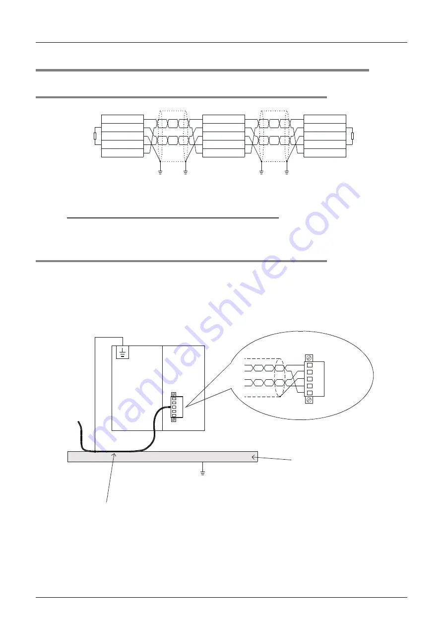
For electromagnetic compatibility (EMC), it is recommended to ground the cable shield at both ends.
Caution
For safety, always check the potential differences between the grounding points. If potential differences are
found, proper measures must be taken to avoid damage.
4.2.2
Module wiring
For further information on PLC wiring, refer to the following manual.
Refer to FX
3G
Hardware Edition
Refer to FX
3GC
Hardware Edition
Refer to FX
3U
Hardware Edition
Refer to FX
3UC
Hardware Edition
Refer to MELSEC iQ-F FX5U User's Manual (Hardware)
Refer to MELSEC iQ-F FX5UC User's Manual (Hardware)
*1.
An FX
2NC
-CNV-IF or FX
3UC
-1PS-5V is necessary to connect the FX
3U
-J1939 to an FX
3GC
/FX
3UC
Series PLC.
*2.
An FX5-CNV-BUS or FX5-CNV-BUSC is necessary to connect the FX
3U
-J1939 to an FX5U/FX5UC
PLC.
Terminating
resistor
Grounding resistance of
100
Ω
or less (Class D)
(1) CAN_GND
(2) CAN_L
(3) CAN_SHLD
(4) CAN_H
(5) CAN_V+
(1) CAN_GND
(2) CAN_L
(3) CAN_SHLD
(4) CAN_H
(5) CAN_V+
(1) CAN_GND
(2) CAN_L
(3) CAN_SHLD
(4) CAN_H
(5) CAN_V+
Grounding resistance of
100
Ω
or less (Class D)
Terminating
resistor
CAN_GND
CAN_L
CAN_SHLD
CAN_H
CAN_V+
Grounding mounting plate or
grounded DIN rail with a
grounding resistance of 100
or less (Class D).
Grounding resistance of
100
or less (Class D)
FX
3G
/FX
3GC
*1
/
*1
/
FX
3U
/FX
3UC
FX5U
*2
/FX5UC
*2
PLC
FX
3U
-J1939
Strip a part of the coating of the shielded twisted pair cable as shown in subsection 4.2.3.
Ground the PLCs grounding terminal there.
CAN Bus connector


