


66
Causes and corrective actions
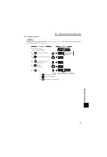
(3) Minor fault
When the protective function is activated, the output is not shut off. You can also output a minor fault signal by
making parameter setting. (Set "98" in any of
Pr. 190 to Pr. 196 (output terminal function selection)
.
(Refer to
Instruction Manual (applied).)
)
(4) Major fault
When the protective function is activated, the inverter output is shut off and an alarm is output.
Operation Panel
Indication
FN
FR-PU04
FN
Name
Fan fault
Description
For the inverter that contains a cooling fan,
appears on the operation panel when the cooling fan
stops due to a fault or different operation from the setting of
Pr. 244 Cooling fan operation selection
.
Check point
Check the cooling fan for a fault.
Corrective action
Check for fan fault. Please contact your sales representative.
Operation Panel
Indication
E.OC1
FR-PU04
OC During Accs
Name
Overcurrent shut-off during acceleration
Description
When the inverter output current reaches or exceeds approximately 170% of the rated current during
acceleration, the protective circuit is activated to stop the inverter output.
Check point
1. Check for sudden acceleration.
2. Check that the downward acceleration time is not long in vertical lift application.
3. Check for output short circuit.
4. Check that stall prevention operation is correct.
5. Check that the regeneration is not performed frequently. (Check that the output voltage becomes
larger than the V/F reference voltage at regeneration and overcurrent due to increase in motor
current occurs.)
Corrective action
1. Increase the acceleration time.
(Shorten the downward acceleration time in vertical lift application.)
2. When "E.OC1" is always lit at starting, disconnect the motor once and start the inverter.
If "E.OC1" is still lit, contact your sales representative.
3. Check the wiring to make sure that output short circuit does not occur.
4. Perform a correct stall prevention operation.
(Refer to
Instruction Manual (applied).)
5. Set base voltage (rated voltage of the motor, etc.) in
Pr. 19 Base frequency voltage
.
(Refer to
Instruction Manual (applied).)
Operation Panel
Indication
E.OC2
FR-PU04
Stedy Spd OC
Name
Overcurrent shut-off during constant speed
Description
When the inverter output current reaches or exceeds approximately 170% of the rated current during
constant speed operation, the protective circuit is activated to stop the inverter output.
Check point
1. Check for sudden load change.
2. Check for output short circuit.
3. Check that stall prevention operation is correct.
Corrective action
1. Keep load stable.
2. Check the wiring to avoid output short circuit.
3. Check that stall prevention operation setting is correct.
(Refer to
Instruction Manual (applied).)
Operation Panel
Indication
E.OC3
FR-PU04
OC During Dec
Name
Overcurrent shut-off during deceleration or stop
Description
When the inverter output current reaches or exceeds approximately 170% of the rated inverter current
during deceleration (other than acceleration or constant speed), the protective circuit is activated to
stop the inverter output.
Check point
1. Check for sudden speed reduction.
2. Check for output short circuit.
3. Check for too fast operation of the motor's mechanical brake.
4. Check that stall prevention operation setting is correct.
Corrective action
1. Increase the deceleration time.
2. Check the wiring to avoid output short circuit.
3. Check the mechanical brake operation.
4. Check that stall prevention operation setting is correct.
(Refer to
Instruction Manual (applied).)
Содержание FR-F 700 EC
Страница 2: ......
Страница 142: ...MEMO ...


