209
9. (F) Settings for Acceleration/Deceleration
9.6 Shortest acceleration/deceleration (automatic acceleration/deceleration)
1
2
3
4
5
6
7
8
9
10
9.6
Shortest acceleration/deceleration (automatic
acceleration/deceleration)
The inverter can be operated with the same conditions as when the appropriate value is set to each parameter even when
acceleration/deceleration time and V/F pattern are not set. This function is useful for operating the inverter without setting
detailed parameters.
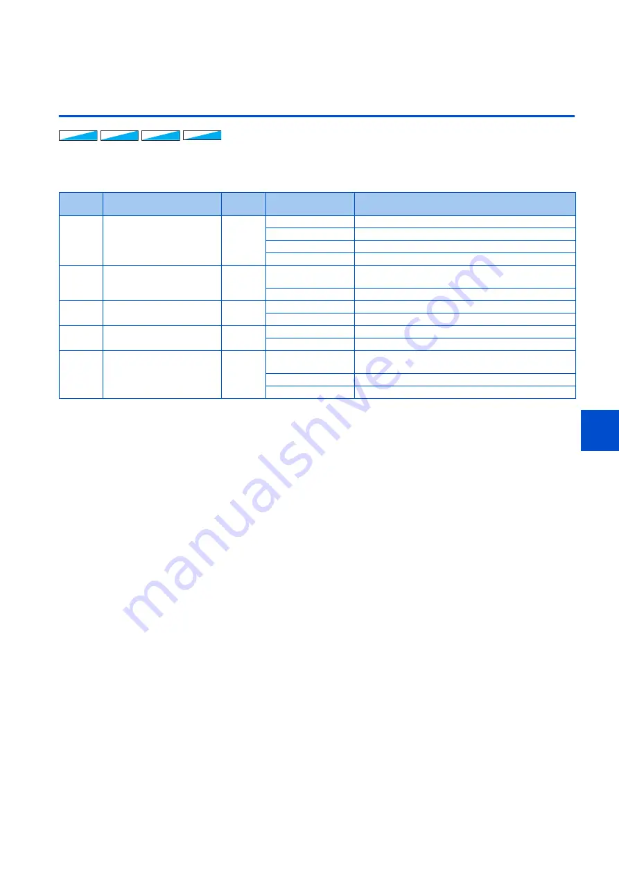
Shortest acceleration/deceleration (Pr.292 = "1, 11", Pr.293)
• Set this parameter to accelerate/decelerate the motor at the shortest time. This function is useful when the motor needs
to be accelerated/decelerated at a shorter time, such as for a machine, but the designed value of the machine constant is
not known.
• At acceleration/deceleration, this function adjusts the motor to accelerate/decelerate with the maximum inverter output
torque using the
Pr.7 Acceleration time
and
Pr.8 Deceleration time
setting as reference. (
Pr.7 and Pr.8
settings are not
changed.)
• Use
Pr.293 Acceleration/deceleration separate selection
to apply the shortest acceleration/deceleration to one of
acceleration and deceleration only.
When "0" (initial value) is set, the shortest acceleration/deceleration is performed for both acceleration and deceleration.
• Set "11" in
Pr.292
when a brake resistor or brake unit is connected. The deceleration time can further be shortened.
• When the shortest acceleration/deceleration is selected under V/F control and Advanced magnetic flux vector control, the
stall prevention operation level during acceleration/deceleration becomes 150% (adjustable using
Pr.61 to Pr.63
). The
setting of
Pr.22 Stall prevention operation level
and stall level by analog input are used only during a constant speed
operation.
Under Real sensorless vector control and Vector control, the torque limit level (
Pr.22
, etc.) is applied during acceleration/
deceleration. The adjustments by
Pr.61 to Pr.63
are disabled.
• It is inappropriate to use for the following applications.
V/F
V/F
V/F
Magnetic flux
Magnetic flux
Magnetic flux Sensorless
Sensorless
Sensorless Vector
Vector
Vector
Pr.
Name
Initial
value
Setting range
Description
292
F500
A110
Automatic acceleration/
deceleration
0
0
Normal operation
1
Shortest acceleration/deceleration (without brakes)
11
Shortest acceleration/deceleration (with brakes)
7, 8
Brake sequence 1, 2 (Refer to
61
F510
Reference current
9999
0 to 500 A
Set the reference current during shortest acceleration/
deceleration.
9999
Rated output current value reference of the inverter
62
F511
Reference value at
acceleration
9999
0% to 400%
Set the speed limit value during shortest acceleration.
9999
The limit value is 150% (120% for the LD rating).
63
F512
Reference value at
deceleration
9999
0% to 400%
Set the speed limit value during shortest deceleration.
9999
The limit value is 150% (120% for the LD rating).
293
F513
Acceleration/deceleration
separate selection
0
0
Shortest acceleration/deceleration for both acceleration
and deceleration
1
Shortest acceleration/deceleration for acceleration only
2
Shortest acceleration/deceleration for deceleration only
- Machines with large inertia (10 times or more), such as a fan. Since stall prevention operation is activated for a long
time, this type of machine may be shut off due to motor overloading, etc.
- When the inverter is always operated at a specified acceleration/deceleration time.
Содержание FR-E800
Страница 17: ...16 1 Introduction 1 3 Related manuals MEMO ...
Страница 51: ...50 2 Basic Operation 2 8 I O terminal function assignment MEMO ...
Страница 89: ...88 3 Parameters 3 4 Parameter list by function group number MEMO ...
Страница 135: ...134 5 Speed Control 5 9 Troubleshooting in the speed control MEMO ...
Страница 153: ...152 6 Torque Control 6 7 Troubleshooting in torque control MEMO ...
Страница 195: ...194 8 E Environment Setting Parameters 8 18 Current average value monitor signal MEMO ...
Страница 237: ...236 10 D Operation Command and Frequency Command 10 6 Operation by multi speed setting MEMO ...
Страница 339: ...338 13 T Multi Function Input Terminal Parameters 13 9 Start signal operation selection MEMO ...
Страница 455: ...454 16 G Control Parameters 16 13 Speed smoothing control MEMO ...
Страница 481: ...480 18 Appendix 18 4 Parameters functions and instruction codes under different control methods MEMO ...


