13
ORIENTATION CONTROL—A500(L)
(3) Connection of terminal resistors.
Use the jumpers across PA2-PAR, PB2-PBR and PC2-PCR to connect terminal resistors to the A, B
and C-phases of the encoder. Normally, keep the jumpers fitted.
However, remove the jumpers when the same encoder is shared between the FR-A5AP and the other
unit (e.g. NC) which is connected with a terminal resistor.
(4) Position detector (encoder).
Line driver LED type encoder
A.
signal 1000ppr to 4096ppr
B.
signal 1000ppr to 4096ppr
Z.
signal 1ppr
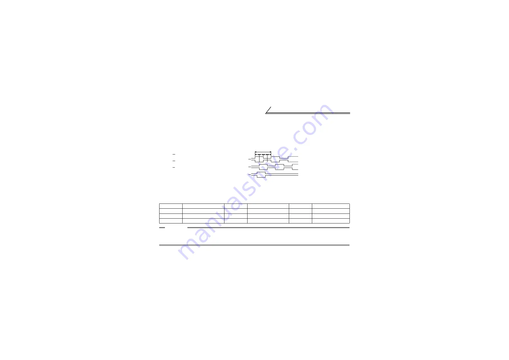
Output pulse specifications
a, b, c and d should be (1/4
±
1/8)P when rotation is clockwise
as viewed from the shaft end of the encoder.
<Example of encoder available on the market>
Use an encoder which has an output circuit equivalent to AM26LS31 or 74LS113.
Pin Numbers of encoder Output Signals
Pin Number
Output Signal
Pin Number
Output Signal
Pin Number
Output Signal
C
A-phase signal
N
B-phase inverse signal
H
+5V power supply
R
A-phase inverse signal
B
Z-phase signal
K
Power supply common
A
B-phase signal
P
Z-phase inverse signal
E
Case earth (ground)
CAUTION
When encoder feedback control and orientation control are used together, the encoder is shared
between these controls.
Use an encoder which has a pulse count of 1000 to 4096ppr (pulses per revolution).
A
B
Z
P
a
b c d
2.4 to 5.25V
H
1000ppr to 4096ppr
1000ppr to 4096ppr
1000ppr to 4096ppr
1000ppr to 4096ppr
1ppr
1ppr
A
A
B
B
Z
Z
L
0 to 0.4V


