


Appendix-670
Spline interpolation
Slot 2
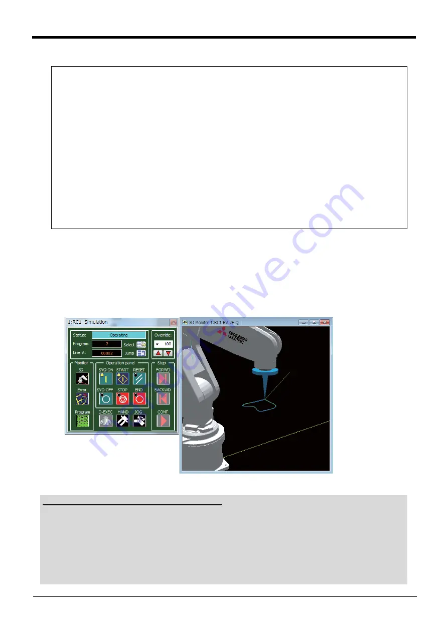
7.3.7 Confirming the movement
Using the RT ToolBox2 simulation function, confirm the spline interpolation movement of the created robot
program. If the movement differs from the required movement, review and correct the path point data set-
tings and robot program.
Refer to the "RT ToolBox2/RT ToolBox2 mini Instruction Manual" for details on using the simulation function.
Note that the simulation function cannot be used with RT ToolBox2 mini.
Fig.7-104:Simulation function
Def IO PORT1=Byte, 100, &H03
‘ Assign output signal 100 and 101 to variable PORT1
M_SplVar=0
‘ Reset M_SplVar value to 0
Wait M_00=1
‘ Wait for spline interpolation to start
*L1:If M_SplPno<3 Then GoTo *L1
‘ Wait for path point 3 to be passed
*L2
Select M_SplVar
Case 1
‘ Pass through path point for which numerical setting value is set
to 1
PORT1=1
‘ Turn output signal 100 ON
Break
Case 2
‘ Pass through path point for which numerical setting value is set
to 2
PORT1=2
‘ Turn output signal 101 ON
Break
Default
‘ Numerical setting value is not 1 or 2
PORT1=0
‘ Turn output signal 100 and 101 OFF
Break
End Select
If M_00=1 Then Goto *L2
‘ Repeat until spline interpolation is finished
End
Robot program and spline file used for simulation
When spline interpolation is simulated, the robot program and spline file must be registered into the vir-
tual controller in the RT ToolBox2. If the robot program and spline file are not registered into the [Online]
section of the project starting the simulation, copy them into the virtual controller with the following
method.
• Robot program: Use the RT ToolBox2 program control.
• Spline file:
Open the target file in the Spline File Edit screen, and save with the procedure give
on
Page 648, "(9) Saving the spline file"
or copy with the procedure gibe on


