background image

GB

F

INSTALLATION MANUAL

For safe and correct use, please read this installation manual thoroughly before installing the air-conditioner unit.

MANUEL D’INSTALLATION

Veuillez lire le manuel d’installation en entier avant d’installer ce climatiseur pour éviter tout accident et vous assurer d’une utilisation correcte.

Air-Conditioners For Building Application
HEAT SOURCE UNIT

PQHY-P-T(S)LMU-A PQRY-P-T(S)LMU-A
PQHY-P-Y(S)LMU-A PQRY-P-Y(S)LMU-A

For use with R410A

Содержание CITY MULTI PQHY-P-TLMU-A

Страница 1: ...tioner unit MANUEL D INSTALLATION Veuillez lire le manuel d installation en entier avant d installer ce climatiseur pour éviter tout accident et vous assurer d une utilisation correcte Air Conditioners For Building Application HEAT SOURCE UNIT PQHY P T S LMU A PQRY P T S LMU A PQHY P Y S LMU A PQRY P Y S LMU A For use with R410A ...

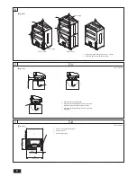
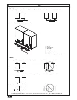
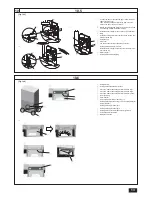
Страница 2: ...nsure that the legs do not bend C Check that the installation leg corners are securely supported C 25 1 or less A B 8QLW PP LQ 8QLW PP LQ A Space for removing the control box B Heat source unit C 6HUYLFH VSDFH IURQW A B C 34 11 16 880 600 450 23 5 8 17 3 4 13 13 16 350 A 6XVSHQVLRQ 5RSHV P IW RU ORQJHU î URSHV B 3URWHFWLYH 3DGV IURQW DQG EDFN SRLQWV P72 P120 P144 P240 ...

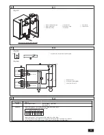
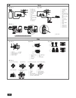
Страница 3: ...The relay closes during reception of cooling or the heating operation signal from the controller 1RWH W RXWSXWV HYHQ LI WKH WKHUPRVWDW LV 2 ZKHQ WKH FRPSUHVVRU LV QRW RSHUDWLQJ A Main circulating water pipe D Water outlet upper G Water inlet lower B Shutoff valve E Refrigerant pipes H Drain pipe C Shutoff valve F Y type strainer C A G D H E B F Heat source unit sample installation Flow switch FS F...

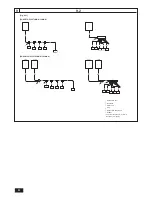
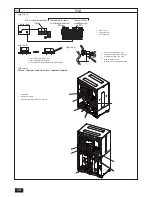
Страница 4: ...D C C C C C A F PQHY P144 P360TSLMU A YSLMU A A1 A2 A a b c d e unit1 unit2 B E D C C C C C A A F C D e A1 A2 A B a b c d unit1 unit2 B E C C C C C A A A Heat source unit B 1st branch C Indoor unit D Cap E Heat source twinning kit F Header The total length of A1 and A2 is less than 10 m 32 ft ...

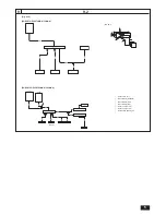
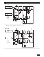
Страница 5: ...C F E E A 127 i j g h B C D F PQRY P144 P336TSLMU A YSLMU A A Heat source unit B FRQWUROOHU VWDQGDUG C FRQWUROOHU PDLQ D FRQWUROOHU VXE E QGRRU XQLW a F QGRRU XQLW a G Heat source twinning kit A1 A2 B C E D A a b c d f e unit1 unit2 NOTE1 G E F C E E E E D D A A ...

Страница 6: ...19 05 3 4 P96T YLMU ø19 05 3 4 ø22 2 7 8 P120T YLMU ø19 05 3 4 ø22 2 7 8 P144T YLMU ø22 2 7 8 ø28 58 1 1 8 P144T YSLMU P72 P72 ø22 2 7 8 ø28 58 1 1 8 ø15 88 5 8 ø19 05 3 4 ø15 88 5 8 ø19 05 3 4 P168T YLMU ø22 2 7 8 ø28 58 1 1 8 P168T YSLMU P96 P72 ø22 2 7 8 ø28 58 1 1 8 ø19 05 3 4 ø22 2 7 8 ø19 05 3 4 ø22 2 7 8 P192T YLMU ø22 2 7 8 ø28 58 1 1 8 P192T YSLMU P96 P96 ø22 2 7 8 ø28 58 1 1 8 ø19 05 3 4...

Страница 7: ...der Downstream indoor unit model total CMY Y104C G CMY Y108C G CMY Y1010C G 345 3ā7 6 08 6 08 8QLW PP LQ Total capacity of indoor units Liquid pipe Gas pipe 54 ø9 52 3 8 ø15 88 5 8 8QLW PP LQ Downstream unit model total High pressure gas pipe Low pressure gas pipe Liquid pipe 72 ø15 88 5 8 ø19 05 3 4 ø9 52 3 8 73 108 ø19 05 3 4 ø22 2 7 8 ø9 52 3 8 109 126 ø19 05 3 4 ø28 58 1 1 8 ø12 7 1 2 127 144 ...

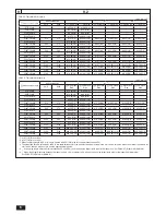
Страница 8: ...aight pipe length that is 500mm 19 11 16 in or more G F E E Fig 9 2 4 A Install the piping so that oil will not accumulate in the stopped heat source unit both the liquid and the gas side for PQHY P TSLMU A YSLMU A WKH KLJK SUHVVXUH VLGH RQO IRU 345 3ā76 08 6 08 1 A C D unit 1 unit 2 C D B unit 1 unit 2 The NG example shows that oil accumulates because the units are installed on a reverse gradient...

Страница 9: ...LQJ SLSHV IRU 34 3ā76 08 6 08 Make sure the slope of the twinning pipes are at an angle within 15 to the horizontal plane If the slope exceeds the angle specified the unit may be damaged 15 D E DPSOH RI SLSLQJ FRQQHFWLRQ IRU 345 3ā76 08 6 08 A Slope downward B Slope upward C FRQWUROOHU VWDQGDUG RU PDLQ D Twinning pipe E Slope of the twinning pipe is at an angle within 15 to the ground F 7ZLQQLQJ S...

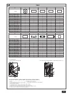
Страница 10: ...QRY P120TLMU A YLMU A 1 B Low pressure side PQRY P144TLMU A YLMU A PQRY P168TLMU A YLMU A PQRY P192TLMU A YLMU A PQRY P216TLMU A YLMU A PQRY P240TLMU A YLMU A No 5 6 7 8 A Shape IDø19 05 ODø19 05 IDø28 6 ODø28 6 IDø25 4 ODø22 2 PQHY P72TLMU A YLMU A 1 PQHY P96TLMU A YLMU A 1 PQHY P120TLMU A YLMU A 1 PQHY P144TLMU A YLMU A 1 PQHY P168TLMU A YLMU A 1 PQHY P192TLMU A YLMU A 1 PQHY P216TLMU A YLMU A 1...

Страница 11: ...MU A 4 4 1 1 1 PQRY P72TLMU A YLMU A 1 1 PQRY P96TLMU A YLMU A 1 1 PQRY P120TLMU A YLMU A 1 1 PQRY P144TLMU A YLMU A 4 4 1 1 1 PQRY P168TLMU A YLMU A 4 4 1 1 1 PQRY P192TLMU A YLMU A 4 4 1 1 1 PQRY P216TLMU A YLMU A 4 4 1 1 1 PQRY P240TLMU A YLMU A 4 4 1 1 1 A Front pipe routing B Without a low pressure twinning pipe C LWK D ORZ SUHVVXUH WZLQQLQJ SLSH 345 3ā76 08 6 08 21 A B B C E F D C B G H I F ...

Страница 12: ...V KROH RQ UH DQG boundary walls A Sleeve B Insulation C Lagging D Caulking material E Band F DWHUSURR QJ OD HU G Sleeve with edge H Lagging material I Mortar or other incombustible caulking J Explosion resistant insulation F H D B G I A J 1m 1m A Siphon pipe B If the R410A cylinder does not have a siphon pipe A Nitrogen gas B To indoor unit C System analyzer D Low knob E High knob F Valve G Low pr...

Страница 13: ... be at the top I Sealing material for water stopper J Install the water stopper so that the slit of the water stop per is at the top K Water stopper L 6HDOLQJ PDWHULDO IRU HOG SLSLQJ 10 6 Fig 10 6 A G C J K I H B L M J F I D E K A Enlarged view B Sealing material attachment process C 3URFHVV WWDFK WKH VHDOLQJ PDWHULDO IRU EDVH OHJ D 3URFHVV WWDFK WKH VHDOLQJ PDWHULDO IRU EDVH OHJ E 3URFHVV WWDFK W...

Страница 14: ...Y P T S LMU A Y S LMU A A A A B C A A A B C A Power source B Transmission line C Ground terminal A Cable strap B Power source cable C URXQG WHUPLQDO IRU HOG ZLULQJ FRQQHFWLRQ A Power wires transmission lines B DLV FKDLQ WUDQVPLVVLRQ OLQHV RQO C 7HUPLQDO EORFNV 7 7 7 D Make an alignment mark E Install the ring terminals back to back A Terminal block with loose screws B Properly installed terminal b...

Страница 15: ...nsmission line for centralized control disconnect the male power supply FRQQHFWRU 1 IURP 21 KHDW VRXUFH XQLW LQ WKH V VWHP DQG FRQQHFW LW WR 1 2 If a system controller is used set SW5 1 on all of the heat source units to ON Fig 11 3 2 PQHY KDQJH WKH MXPSHU FRQQHFWRU from CN41 to CN40 1 B SW5 1 ON 2 HHS WKH MXPSHU FRQQHFWRU on CN41 B SW5 1 ON 2 A B C E D M1 M2 M1 M2 M1M2 S TB7 TB3 IC 51 M1M2 1 2 S ...

Страница 16: ... CN41 53 OC A B S System controller L3 L 6 L4 L 5 A B A B A B A B BC M1M2S 52 BS M1M2S 55 BC M1M2S 54 TB02 TB02 TB02 3 2 4 1 OC CN41 CN41 CN40 A Group 1 B Group 3 C Group 5 D Shielded wire E Sub remote controller GGUHVV 1 When the power supply unit is not connected to the transmission line for centralized control disconnect the male power supply FRQQHFWRU 1 IURP 21 KHDW VRXUFH XQLW LQ WKH V VWHP D...

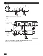
Страница 17: ...TB5 IC M1M2 S TB5 RP Ground A B A B A B S TB2 A B S TB3 L 15 L 18 ME IC M1M2 S TB5 IC M1M2 S TB5 L17 L16 L14 L13 M1M2 S M1 M2 TB3 M1 M2 TB3 M1M2 S TB7 M1M2 S TB7 OC 51 L11 L12 OS 52 CN41 CN41 TB02 To another refrigerant system 1 1 11 4 Fig 11 4 1 A Switch Breakers for wiring DQG FXUUHQW OHDNDJH B Breakers for current leakage C Heat source unit D Pull box E Indoor unit F BC controller VWDQGDUG RU P...

Страница 18: ...source capacity is inadequate or electric work is performed LPSURSHUO HOHFWULF VKRFN DQG UH PD UHVXOW Keep the electric parts away from water washing water etc W PLJKW UHVXOW LQ HOHFWULF VKRFN FDWFKLQJ UH RU VPRNH Securely install the heat source unit terminal cover panel I WKH WHUPLQDO FRYHU SDQHO LV QRW LQVWDOOHG SURSHUO GXVW RU ZDWHU PD HQWHU WKH KHDW VRXUFH XQLW DQG UH RU HOHFWULF VKRFN PD UHV...

Страница 19: ...e of the compressor during servicing If unit is connected to a supply and not running the crank case heater located at the base of the compressor may still be operating 1 2 Precautions for devices that use R410A refrigerant Caution Do not use existing refrigerant piping The old refrigerant and refrigerant oil in the existing piping contains a large amount of chlorine which may cause the refrigeran...

Страница 20: ...ted below Model name module PQRY P72TLMU A PQRY P96TLMU A PQRY P120TLMU A PQRY P144TLMU A PQRY P144TSLMU A PQRY P72TLMU A PQRY P72TLMU A PQRY P168TLMU A PQRY P168TSLMU A PQRY P96TLMU A PQRY P72TLMU A PQRY P192TLMU A PQRY P192TSLMU A PQRY P96TLMU A PQRY P96TLMU A PQRY P216TLMU A PQRY P216TSLMU A PQRY P120TLMU A PQRY P96TLMU A PQRY P240TLMU A PQRY P240TSLMU A PQRY P120TLMU A PQRY P120TLMU A PQRY P28...

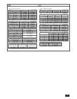
Страница 21: ... Water temperature 10 C 45 C 50 F 113 F 1 The total indoor capacity of units run simultaneously is 130 or less PQHY P YLMU A Model PQHY P72YLMU A PQHY P96YLMU A PQHY P120YLMU A PQHY P144YLMU A PQHY P168YLMU A PQHY P192YLMU A PQHY P216YLMU A PQHY P240YLMU A Sound pressure level 46dB A 48dB A 54dB A 54dB A 56dB A 58dB A 58dB A 58dB A Net weight 185kg 408LBS 230kg 508LBS 260kg 574LBS Maximum water pr...

Страница 22: ...l indoor capacity of units run simultaneously is 150 or less 2 Connectable branch pipe number is max 48 PQRY P YLMU A Model PQRY P72YLMU A PQRY P96YLMU A PQRY P120YLMU A PQRY P144YLMU A PQRY P168YLMU A PQRY P192YLMU A PQRY P216YLMU A PQRY P240YLMU A Sound pressure level 46dB A 48dB A 54dB A 54dB A 56dB A 58dB A 58dB A 58dB A Net weight 183kg 404LBS 229kg 505LBS 259kg 571LBS Maximum water pressure ...

Страница 23: ...al IRU HOG SLSLQJ Gas side d Sealing material for base leg e Sealing material for base leg f Sealing material for water panel g Pipe cover Gas side h Sealing material for drain socket P72 1 pc 1 pc 1 pc 1 pc 1 pc 1 pc P96 1 pc 1 pc 1 pc 1 pc 1 pc 1 pc P120 1 pc 1 pc 1 pc 1 pc 1 pc 1 pc P144 1 pc 1 pc 1 pc 1 pc 4 pc 4 pc 1 pc 1 pc 1 pc P168 1 pc 1 pc 1 pc 1 pc 4 pc 4 pc 1 pc 1 pc 1 pc P192 1 pc 1 p...

Страница 24: ...d possible corrosion Pay careful attention to water processing and water quality control when installing the water circulation system 5HPRYLQJ RI IRUHLJQ REMHFWV RU LPSXULWLHV ZLWKLQ WKH SLSHV XULQJ LQVWDOODWLRQ PDNH VXUH WKDW IRUHLJQ REMHFWV VXFK DV ZHOGLQJ fragments sealant particles or rust do not enter the pipes Water Quality Processing 1 Depending on the quality of the cold temperature water ...

Страница 25: ...Never weld in an unventilated room Always conduct an inspection for gas leakage after installation of the refrigerant piping has been completed 9 1 Caution This unit uses refrigerant R410A Follow the local regulations on materials and pipe thickness when selecting pipes 5HIHU WR WKH WDEOH EHORZ 1 Use the following materials for refrigeration piping Material Use copper alloy seamless pipes made of ...

Страница 26: ... D Cap E Heat source twinning kit F Header 1 ø12 7 for over 90 m 295 1 4in 2 ø12 7 for over 40 m 131 3 16in 3 The pipe sizes listed in columns A1 to A2 in this table correspond to the sizes for the models listed in the unit 1 and 2 columns When the order of the models for unit 1 and 2 change make sure to use the appropriate pipe size 4 B I WKH SLSLQJ OHQJWK DIWHU WKH UVW MRLQW H FHHGV P P XVH WKH ...

Страница 27: ... 88 mm 5 8in Liquid Piping Size Total length of ø12 7 mm 1 2in A P î NJ P IW î R IW A P î NJ P IW î R IW A P î NJ P IW î R IW B P î NJ P IW î R IW B P î NJ P IW î R IW B P î NJ P IW î R IW Liquid Piping Size Total length of ø9 52 mm 3 8in Liquid Piping Size Total length of ø6 35 mm 1 4in A P î NJ P IW î R IW A P î NJ P IW î R IW B P î NJ P IW î R IW B P î NJ P IW î R IW Additional charge Heat sour...

Страница 28: ...emove the pinched connecting pipe before connecting refrigerant pipes to the heat source unit 1 KHFN WKDW WKH UHIULJHUDQW VHUYLFH YDOYH LV IXOO FORVHG FORFNZLVH 2 Connect a charging hose to the service port on the low pressure high pressure liquid gas refrigerant service valve and extract the gas in the piping between the refrigerant service valve and the pinched FRQQHFWLQJ SLSH 7LJKWHQLQJ WRUTXH ...

Страница 29: ...sure liquid pipe F High pressure gas pipe G Service port H 7KUHH ZD MRLQW I Valve J Valve K R410A cylinder L Scale M Vacuum pump N To indoor unit O Heat source unit Note Always add the appropriate amount of refrigerant Also always charge the system with liquid refrigerant Use a gauge manifold charging hose and other parts for the refrigerant indicated on the unit Use a graviometer One that can mea...

Страница 30: ... to both liquid pipe and gas pipe 8VH WKH ZDWHU VWRSSHUV DQG VHDOLQJ PDWHULDO WKDW W HDFK SLSH Fig 10 5 P 13 A Position the edge of the supplied paper with mark at the edge of the pipe cover Then wind the sealing material to the pipe using the mark on the paper to properly align it B WHQG WKH HOG VXSSOLHG LQVXODWLRQ DOO WKH ZD WR WKH HQG RI WKH VHDOLQJ material described in step A C Install the wa...

Страница 31: ...UHZV WR WKH VSHFL HG WRUTXH 7HUPLQDO EORFN 7 7 08 0 VFUHZ a 1āP 7HUPLQDO EORFN 7 08 0 VFUHZ a 1āP 7HUPLQDO EORFN 7 7 0 VFUHZ a 1āP Make sure that the spring washers are parallel to the terminal block Make sure that the wires are securely fastened to the terminal screws Drive the screws straight down and use caution not to damage the screw heads Install the ring terminals back to back so that the s...

Страница 32: ...RQ WKH UHPRWH FRQWUROOHU 5 G RQQHFW WRJHWKHU WHUPLQDOV 0 0 DQG WHUPLQDO 6 RQ WKH WHUPLQDO EORFN IRU FHQWUDO FRQWURO 7 IRU WKH KHDW VRXUFH XQLW LQ D GLIIHUHQW UHIULJHUDQW V VWHP 2 RU OC and OS in the same refrigerant system connect TB7 to TB7 H KHQ WKH SRZHU VXSSO XQLW LV QRW LQVWDOOHG RQ WKH FHQWUDO FRQWURO WUDQVPLVVLRQ OLQH FKDQJH WKH MXPSHU FRQQHFWRU RQ WKH FRQWURO ERDUG IURP 1 WR 1 RQ RQO one h...

Страница 33: ...ire for main power supply capacities of the switch and system impedance MOP is used to select the fuse switch or breaker for current leakage Model Minimum wire thickness mm2 0 023 Main cable Branch Ground WY PQHY P72TLMU A 3 3 12 3 3 12 13 20 PQHY P96TLMU A 5 3 10 5 3 10 19 30 PQHY P120TLMU A 8 4 8 8 4 8 29 50 PQHY P144TLMU A 13 3 6 13 3 6 35 60 PQHY P168TLMU A 13 3 6 13 3 6 44 70 PQHY P192TLMU A ...

Страница 34: ...tat OFF Light air automatically changes over to set value by time or piping temperature at thermostat ON Fan does not stop while operation has been stopped No lighting The fan is set to run for 1 minute after stopping to exhaust residual heat only LQ KHDWLQJ No setting of fan while start SW has been turned on Heat ready Ultra low speed operation for 5 minutes after SW ON or until piping temperatur...

Страница 35: ... NJ 6 R 6 R NJ NJ 6 R 6 R Allowable SUHVVXUH 3V HP 4 15MPa 601psi LP 2 21MPa 320psi Net weight 185kg 185kg 408LBS 408LBS 230kg 230kg 508LBS 508LBS PQRY P TLMU A individual unit PQRY P72TLMU A PQRY P96TLMU A PQRY P120TLMU A PQRY P144TLMU A PQRY P168TLMU A PQRY P192TLMU A PQRY P216TLMU A PQRY P240TLMU A Module set 5HIULJHUDQW 5 5 0kg 11LBS 1oz 6 0kg 13LBS 4oz 11 7kg 25LBS 13oz Allowable SUHVVXUH 3V ...

Страница 36: ...tricien licencié selon les Normes techniques des installations électriques les Règlements relatifs aux câblages intérieurs et les instructions données dans ce manuel et utilisez toujours une alimentation dédiée Si la source d énergie est inadéquate ou les travaux électriques sont exécutés incorrectement un risque de choc électrique et d incendie peut en résulter Maintenez les pièces électriques à ...

Страница 37: ...l unité sur ou au dessus de choses sujettes à l endommagement par l eau Quand l humidité de la pièce excède 80 ou lorsque le drain est obstrué la condensation peut s égoutter d une unité d intérieur Exécutez un travail de drainage collectif avec l unité extérieure selon besoins 1 4 Avant l installation déménagement travaux électriques Attention Mettez l unité à la terre 1H FRQQHFWH SDV OH O GH WHU...

Страница 38: ...P168TLMU A PQHY P168TLMU A PQHY P360TSLMU A PQHY P192TLMU A PQHY P168TLMU A Les modules PQRY P72 à P336 TLMU A sont listés ci dessous Nom de modèle Module PQRY P72TLMU A PQRY P96TLMU A PQRY P120TLMU A PQRY P144TLMU A PQRY P144TSLMU A PQRY P72TLMU A PQRY P72TLMU A PQRY P168TLMU A PQRY P168TSLMU A PQRY P96TLMU A PQRY P72TLMU A PQRY P192TLMU A PQRY P192TSLMU A PQRY P96TLMU A PQRY P96TLMU A PQRY P216T...

Страница 39: ...n 10 C 45 C 50 F 113 F 1 La capacité totale d unités d intérieur fonctionnant simultanément est au plus de 130 PQHY P YLMU A Modèle PQHY P72YLMU A PQHY P96YLMU A PQHY P120YLMU A PQHY P144YLMU A PQHY P168YLMU A PQHY P192YLMU A PQHY P216YLMU A PQHY P240YLMU A Niveau de pression sonore 46dB A 48dB A 54dB A 54dB A 56dB A 58dB A 58dB A 58dB A Poids net 185kg 408LBS 230kg 508LBS 260kg 574LBS Pression hy...

Страница 40: ...imultanément est au plus de 150 2 Le nombre maximum de tuyau de dérivation pouvant être raccordé est 48 PQRY P YLMU A Modèle PQRY P72YLMU A PQRY P96YLMU A PQRY P120YLMU A PQRY P144YLMU A PQRY P168YLMU A PQRY P192YLMU A PQRY P216YLMU A PQRY P240YLMU A Niveau de pression sonore 46dB A 48dB A 54dB A 54dB A 56dB A 58dB A 58dB A 58dB A Poids net 183kg 404LBS 229kg 505LBS 259kg 571LBS Pression hydrauliq...

Страница 41: ...bilisation pour les pieds de la base e Matériel d imperméabilisation pour les pieds de la base f Matériel d imperméabilisation pour les panneaux à eau g Housse du tuyau côté gaz h Matériel d imperméabilisation pour douille de vidange P72 1 pc 1 pc 1 pc 1 pc 1 pc 1 pc P96 1 pc 1 pc 1 pc 1 pc 1 pc 1 pc P120 1 pc 1 pc 1 pc 1 pc 1 pc 1 pc P144 1 pc 1 pc 1 pc 1 pc 4 pc 4 pc 1 pc 1 pc 1 pc P168 1 pc 1 p...

Страница 42: ...nités extérieures et de la tuyauterie sur site appliquez un matériau d étanchéité liquide pour tuyauterie d eau sur le ruban d étanchéité avant la connexion Exemple d installation de la source de chaleur lors de la mise en place des tuyaux par la gauche Fig 8 1 1 P 3 A Conduite de circulation d eau principale B Vanne d arrêt C Vanne d arrêt D 6RUWLH G HDX VXSpULHXUH E Tuyaux de réfrigérant F Vanne...

Страница 43: ...e indétectables doivent être indétectables c Ions d ammonium mg NH4 Ɛ 0 3 ou moins 0 1 ou moins c Chlore résiduel PJ O Ɛ 0 25 ou moins 0 3 ou moins c Gaz carbonique à l état libre mg CO2 Ɛ 0 4 ou moins 4 0 ou moins c Indice de stabilité Ryzner c c Référence Directive relative à la qualité de l eau pour le matériel de UpIULJpUDWLRQ HW GH FOLPDWLVDWLRQ 5 3 Contacter un spécialiste du contrôle de la ...

Страница 44: ... 05 ø3 4 1 2 48 Type O ø19 05 ø3 4 1 0 40 Type 1 2H ou H ø22 2 ø7 8 1 0 40 Type 1 2H ou H ø25 4 ø1 1 0 40 Type 1 2H ou H ø28 58 ø1 1 8 1 0 40 Type 1 2H ou H ø31 75 ø1 1 4 1 1 44 Type 1 2H ou H ø34 93 ø1 3 8 1 2 48 Type 1 2H ou H ø41 28 ø1 5 8 1 4 56 Type 1 2H ou H Les deux types de tube peuvent être utilisés pour une taille de tube de ø19 05 LQ SRXU OH FOLPDWLVHXU 5 6 8WLOLVH XQ UDFFRUG VL XQ WXEH...

Страница 45: ...re B RQWU OHXU VWDQGDUG C RQWU OHXU SULQFLSDO D RQWU OHXU VHFRQGDLUH E SSDUHLO LQWpULHXU a F SSDUHLO LQWpULHXU a G LW GH MXPHODJH GH OD VRXUFH GH FKDOHXU 1 Lorsque la longueur de la tuyauterie est de 65 m ou plus utilisez le tuyau de ø28 58 1 1 8 pour la partie qui dépasse les 65 m 2 Les tailles de tube listées dans les colonnes A1 à A2 de ce tableau correspondent aux tailles des modèles listés da...

Страница 46: ...de ø15 88 mm 5 8in 7DLOOH GH WXEH GH ÀXLGH Longueur totale de ø15 88 mm 5 8in 7DLOOH GH WXEH GH ÀXLGH Longueur totale de ø12 7 mm 1 2in A P î NJ P IW î R IW A P î NJ P IW î R IW A P î NJ P IW î R IW B P î NJ P IW î R IW B P î NJ P IW î R IW B P î NJ P IW î R IW 7DLOOH GH WXEH GH ÀXLGH Longueur totale de ø9 52 mm 3 8in 7DLOOH GH WXEH GH ÀXLGH Longueur totale de ø6 35 mm 1 4in A P î NJ P IW î R IW A...

Страница 47: ... de connexion rétréci avant de connecter les tubes de frigorigène à l unité extérieure 1 9pUL H TXH OD YDOYH GH IULJRULJqQH HVW FRPSOqWHPHQW IHUPpH VHQV KRUDLUH 2 Branchez un tube de remplissage au port de service sur la valve basse pression haute pression liquide gaz et extrayez le gaz dans la section de tuyauterie située entre la valve de frigorigène et le tube de connexion UpWUpFL FRXSOH GH VHU...

Страница 48: ... jauge micron doit être utilisée en permanence DVVH OH YLGH DYHF GH O D RWH 1 GDQV OD YDOYH GH VHUYLFH GH GpFKDUJH MXVTX j 36 Évacuez le système de 1 500 microns par la valve d aspiration DVVH OH YLGH DYHF GH O D RWH 1 GDQV OD YDOYH GH VHUYLFH GH GpFKDUJH MXVTX j 36 Évacuez le système de 500 microns Le système doit maintenir le vide à 500 microns pendant au moins 1 heure Exécutez un test d échauff...

Страница 49: ...l embout conique de sorte que la fente de celui ci soit en haut K Embout conique L Matériel d imperméabilisation pour le tube fourni sur site 10 6 Installation du matériel d imperméabilisation pour les pieds de la base Fig 10 6 P 13 A Vue élargie B 3URFHVVXV GH DWLRQ GX PDWpULDX LVRODQW C 3URFHVVXV L HU OH PDWpULDX LVRODQW SRXU OD MDPEH GH EDVH D 3URFHVVXV L HU OH PDWpULDX LVRODQW SRXU OD MDPEH GH...

Страница 50: ...n panne ou l alimentation est coupée la commande centralisée n est pas exploitable même lorsque le TB7 est FRQQHFWp HQ VpULH 2 HW 26 GHV DSSDUHLOV H WpULHXUV GDQV OH PrPH V VWqPH IULJRUL TXH VRQW DXWRPDWLTXHPHQW LGHQWL pV OV VRQW LGHQWL pV FRPPH 2 HW 26 dans l ordre décroissant de capacité si la capacité est identique ils sont classés dans l ordre ascendant de leur numéro d aGUHVVH 4 Dans le cas d...

Страница 51: ...VPLVVLRQ 53 SHXW V DYpUHU QpFHVVDLUH 2 HW 26 GHV DSSDUHLOV H WpULHXUV GDQV OH PrPH V VWqPH IULJRUL TXH VRQW DXWRPDWLTXHPHQW LGHQWL pV OV VRQW LGHQWL pV FRPPH 2 HW 26 GDQV O RUGUH GpFURLVVDQW GH FDSDFLWp 6L OD FDSDFLWp HVW LGHQWLTXH LOV VRQW FODVVpV GDQV O RUGUH DVFHQGDQW GH OHXU QXPpUR G DGUHVVH Exemple de système d exploitation avec plusieurs appareils extérieurs il est nécessaire d utiliser des ...

Страница 52: ...t impédance du système MOP est utilisé pour sélectionner le fusible le commutateur le coupe circuit pour la fuite courant Modèle Épaisseur minimale du câble mm2 0 023 Câble principal Dérivation Terre WY PQHY P72TLMU A 3 3 12 3 3 12 13 20 PQHY P96TLMU A 5 3 10 5 3 10 19 30 PQHY P120TLMU A 8 4 8 8 4 8 29 50 PQHY P144TLMU A 13 3 6 13 3 6 35 60 PQHY P168TLMU A 13 3 6 13 3 6 44 70 PQHY P192TLMU A 21 2 ...

Страница 53: ... 8Q VRXIÀH G DLU OpJHU SDVVH j OD YDOHXU WHPSRUHOOH SUpGp QLH RX j OD température de la tuyauterie lorsque le thermostat est activé Le ventilateur ne s arrête pas alors que le fonctionnement a été arrêté Aucun éclairage Le ventilateur est programmé pour continuer de fonctionner pendant 1 minute DSUqV O DUUrW GH O DSSDUHLO D Q G pYDFXHU WRXWH FKDOHXU UpVLGXHOOH VHXOHPHQW HQ PRGH GH FKDXIIDJH Ventil...

Страница 54: ... 5 NJ NJ 6 R 6 R NJ NJ 6 R 6 R Pression DGPLVVLEOH 3V HP 4 15MPa 601psi LP 2 21MPa 320psi Poids net 185kg 185kg 408LBS 408LBS 230kg 230kg 508LBS 508LBS PQRY P TLMU A 8QLWp LQGLYLGXHOOH PQRY P72TLMU A PQRY P96TLMU A PQRY P120TLMU A PQRY P144TLMU A PQRY P168TLMU A PQRY P192TLMU A PQRY P216TLMU A PQRY P240TLMU A Ensemble de module ULJRULJqQH 5 5 0kg 11LBS 1oz 6 0kg 13LBS 4oz 11 7kg 25LBS 13oz Pressio...

Страница 55: ......

Страница 56: ...ne number on this manual before handing it to the customer HEAD OFFICE TOKYO BLDG 2 7 3 MARUNOUCHI CHIYODA KU TOKYO 100 8310 JAPAN WT07800X01 This product is designed and intended for use in the residential commercial and light industrial environment ...

Отзывы: