9-94
9-94
9. Connecting to the Robot
This explains the method for connecting the robot controller and the computer.
With this software, you must make the communication settings for each project.
9.1. Robots Connected and Types of Communication
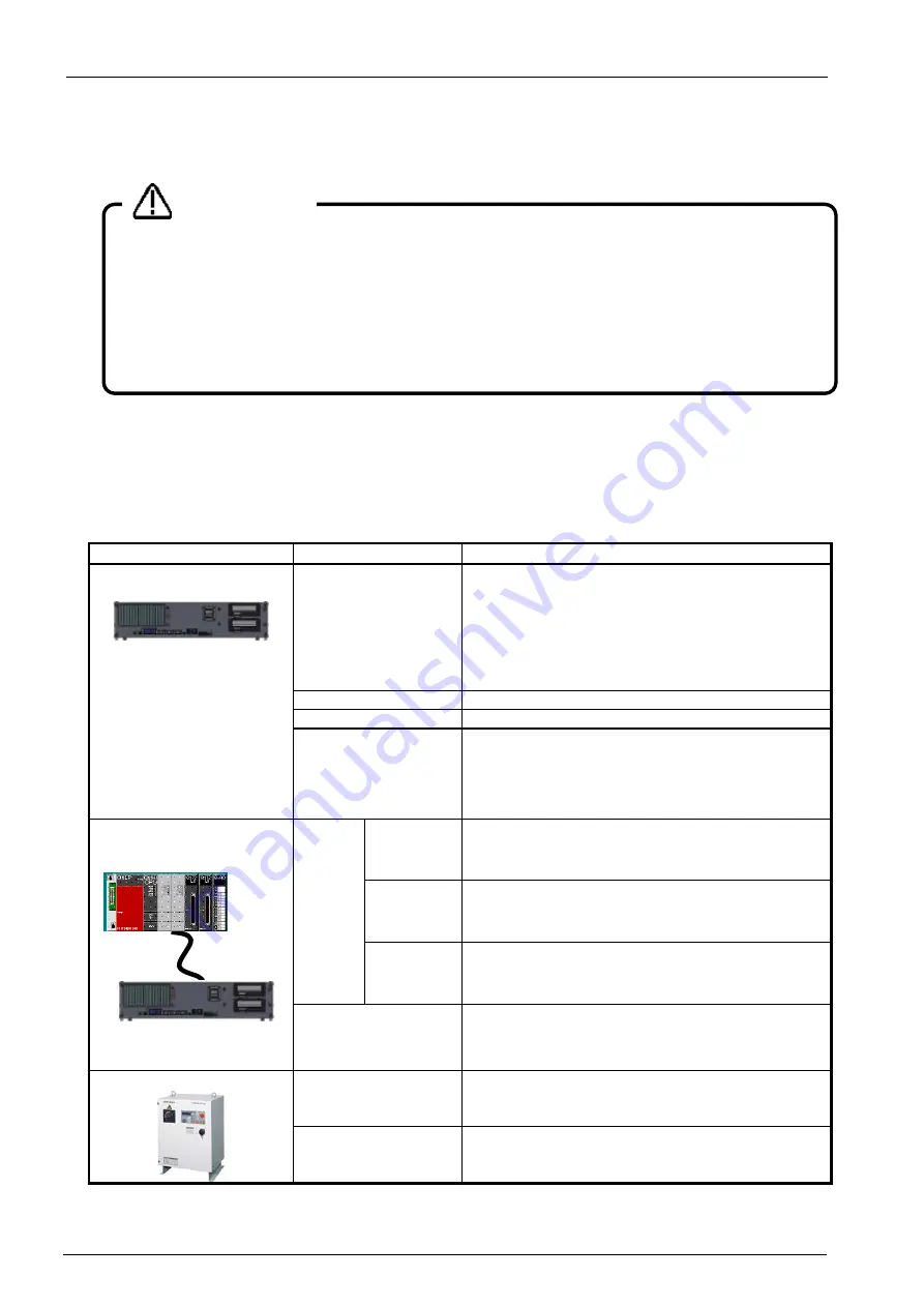
Connecting the robot controller and computer can be done by the following methods. Be aware that the available
connection method is restricted according to the connected robot controller.
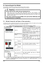
Table 9-1 Robot Controllers That Can Be Connected and Types of Communication
Robot Controller
Communication Type
Remarks
CR800-D/CR750-D/
CRnD-700 series
(The photo is the robot
controller for CR800-D.)
USB (*4)
Commercial items such as computers and cables
might be incompatible with our equipment or
unsuitable for the FA environment such as
temperature, noise, etc.
When using, please fully confirm operation as
measures against noise such as EMI measure or
addition of ferrite core may be needed.
Ethernet(TCP/IP) (*1)
RS-232
CRnD-700 only
GOT communications
Connect via a CR800-D/CR750-D/CRnD-700
series controller connected with the GOT via
Ethernet by USB / RS-232.
A
GOT 1000 series and the Ethernet
communication unit (GT15-J1E71-100) are needed.
CR800-R/CR800-Q/
CR750-Q/CRnQ-700
series
(Pictured is a CR800-R
robot controller.)
CRnQ_
R
commu
nication
(*2)
USB (*4)
Ethernet
(TCP/IP)
The PLC RCPU, Ethernet interface module or
Built-in Ethernet port QCPU is required.
RS-232
Ethernet(TCP/IP)
Only can be used for CR800-R/CR800-Q
CRn-500 series
Ethernet(TCP/IP) (*3)
The robot controller must have an "Ethernet
interface" option.
RS-232
(*1) For details on the communication settings on the robot controller side for CR800-D/CR750-D/CRnD-700 series
controllers, see
"Detailed explanations of functions and operations"
and
"Standard Specifications"
in the user's
manual for the robot controller.
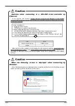
Do not pull out the cable during communication.
Please never pull out the cable during communication with the robot controller. If the
communication cable is removed during communication, the status of the robot controller or the
computer might become abnormal. Please remove the cable when the status is not “Online” or this
software has been exited.
Also when communicating by USB, do not pull out the USB cable until
communication is completed.
Caution
Содержание 3F-14C-WINE
Страница 84: ...8 84 8 84 Figure 8 21 Parameter transfer procedure 1 2 2 ...
Страница 393: ...18 393 18 393 Figure 18 1 Starting the Oscillograph ...
Страница 413: ...18 413 18 413 Figure 18 24 Output to Robot program Selection ...
Страница 464: ...18 464 18 464 Figure 18 72 Starting the Tool automatic calculation ...
Страница 545: ...21 545 21 545 Figure 21 55 Hide display of user mechanism ...
Страница 624: ...24 624 24 624 Figure 24 4 Document output example ...

