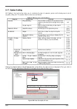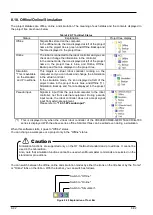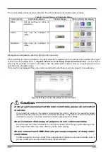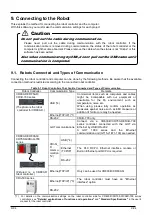
8-81
8-81
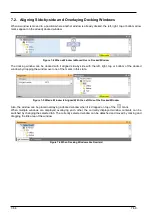
8.9.5. Step 5. Travel axis
Set the travel base to be displayed in the 3D monitor. For details, refer to
"9.2.6 Travel base setting for display"
.
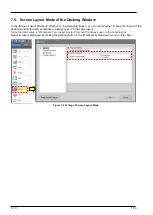
Figure 8-16 Add Project Screen (Step 5. Travel axis)
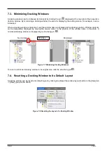
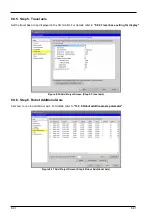
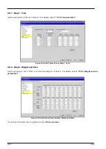
8.9.6. Step 6. Robot Additional Axis
Sets how to use the additional axis.
For details, refer to
"13.3.9 Robot additional axis parameter"
.
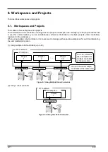
Figure 8-17 Add Project Screen (Step 6. Robot Additional Axis)
Содержание 3F-14C-WINE
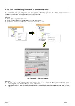
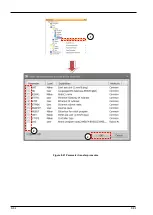
Страница 84: ...8 84 8 84 Figure 8 21 Parameter transfer procedure 1 2 2 ...
Страница 393: ...18 393 18 393 Figure 18 1 Starting the Oscillograph ...
Страница 413: ...18 413 18 413 Figure 18 24 Output to Robot program Selection ...
Страница 464: ...18 464 18 464 Figure 18 72 Starting the Tool automatic calculation ...
Страница 545: ...21 545 21 545 Figure 21 55 Hide display of user mechanism ...
Страница 624: ...24 624 24 624 Figure 24 4 Document output example ...


