7
6
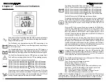
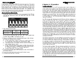
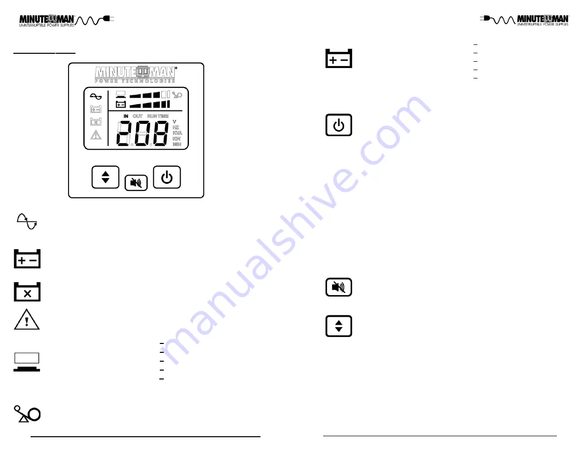
The AC normal icon illuminates when the UPS is on and operating in
the AC normal mode. The AC normal icon will extinguish when oper-
ating in the Battery mode.
The On-Battery icon illuminates when the UPS is operating in the
Battery mode. The On-Battery icon will extinguish when operating in
the AC normal mode.
The Weak/Bad Battery icon illuminates when the UPS detects a
weak battery, bad battery or if the battery is disconnected. The Weak/
Bad Battery icon is extinguished when the battery's condition is good.
The Fault icon illuminates when the UPS detects an internal fault.
The Fault icon is extinguished when the UPS is operating properly.
The Load Level Bar Graph operates as follows:
LED #1: When the attached load is >20% the LED will illuminate.
LED #2: When the attached load is >40% the LED will illuminate.
LED #3: When the attached load is >60% the LED will illuminate.
LED #4: When the attached load is >80% the LED will illuminate.
LED #5: When the attached load is >100% the LED will illuminate.
When the amount of load attached to the UPS exceeds 110% of its
power rating; the Overload icon will flash Off and On, all of the LEDs
in the Load Level Bar Graph will be illuminated and the UPS will
sound a constant alarm to indicate an Overload condition.
The Battery Capacity Bar Graph operates as follows:
LED #1: When the battery capacity is >20% the LED will illuminate.
LED #2: When the battery capacity is >40% the LED will illuminate.
LED #3: When the battery capacity is >60% the LED will illuminate.
LED #4: When the battery capacity is >80% the LED will illuminate.
LED #5: When the battery capacity is >100% the LED will illuminate.
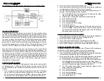
The Multi-Function On/Off/Test Button functions as follows:
Turning the input circuit breaker (on the rear panel) to the on position will
put the UPS in the Bypass mode and supply power to the load. Press,
hold and then release the On/Off/Test Button during the audible alarm's
first beep to turn the inverter on and transfer the UPS to the On-Line
mode.
When the UPS is On, press, hold and then release the On/Off/Test But-
ton during the audible alarm's second beep to turn the inverter off and
transfer the UPS to the Bypass mode. To turn the UPS off turn off the
input circuit breaker on the rear panel, wait for approximately 1-minute
until the LCD and the fans turn off, and then turn off the DC breaker(s) on
the rear panel of the Battery Pack(s).
When the UPS is in the On-Line mode or the Economy mode, press,
hold and then release the On/Off/Test Button during the audible alarm's
forth beep. The UPS will perform a 10-second Self Test. During the test,
the UPS will switch to the Battery mode, the On-Battery icon will illumi-
nate and the audible alarm will sound. If the UPS fails the test, one of the
icons will remain illuminated indicating the type of problem.
Pressing the Alarm Silencer Button while the unit is operating in Battery
mode, will silence the audible alarm. Once the UPS reaches the LBW
(Low Battery Warning) threshold the alarm will be re-activated. The alarm
cannot be silenced during the LBW alarm. Once the UPS transfers to
the AC mode the alarm will be reset to default.
The Scroll Button allows the user to scroll through the UPS parameters
that are available on the LCD screen.
CONTROL PANEL
Chapter 2: Controls and Indicators
NOTE:
The LCD backlight will illuminate for 1-minute when the UPS switches to
the Battery mode. When the UPS has an event and/or an error code the LCD
backlight will turn on and remain on to alert the user that an event has occurred.
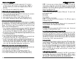
The LCD will report the following information:
INPUT: Voltage, frequency, KVA, KW.
OUTPUT: Voltage, frequency, KVA, KW.
Estimated Runtime: In the normal AC mode and the Battery mode.
Error codes: The UPS will display error codes if an error occurs.
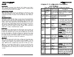
bPS: The UPS is operating in the Bypass mode.
EPo: The Emergency Power Off function is being performed.
ECo: The UPS is operating in the Economy mode.

