5
4
LIFE SUPPORT POLICY
As a general policy, Para Systems does not recommend the use of any of our
products in life support applications where failure or malfunction of the product
can be reasonably expected to cause failure of the life support device or to
significantly affect its safety or effectiveness. We do not recommend the use of
any of our products in direct patient care. We will not knowingly sell our prod-
ucts for use in such applications unless it receives in writing assurances satis-
factory to us that (a) the risks of injury or damage have been minimized, (b) the
customer assumes all such risks, and (c) our liability is adequately protected
under the circumstances.
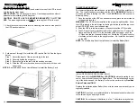
Once you receive the product it should be visually inspected for damage that
may have occurred in shipping. Immediately notify the carrier and place of
purchase if any damage is found. Warranty claims for damage caused by the
carrier will not be honored by the manufacturer. The packing materials that
the product was shipped in were carefully designed to minimize any shipping
damage. In the unlikely case that the product needs to be returned to the
manufacturer, use the original packing material. Since the manufacturer is
not responsible for shipping damage incurred when the product is returned,
the original packing material is inexpensive insurance.
PLEASE SAVE THE
PACKING MATERIALS!
RECIEVING INSPECTION
NOTICE:
This equipment has been tested and found to comply with the limits for
a Class B computing device in accordance with the specifications in Subpart J of
Part 15 of FCC Rules and the Class B limits for radio noise emissions from digital
apparatus set out in the Radio Interference of the Canadian Department of Com-
munications. These limits are designed to provide reasonable protection against
such interference in a residential installation. This equipment generates and uses
radio frequency and if not installed and used properly, that is, in strict accordance
with the manufacturer's instructions, this equipment may cause interference to ra-
dio and television reception. If this equipment does cause interference to radio or
television reception, which can be determined by turning the equipment off and on,
the user is encouraged to try to correct the interference by one or more of the follow-
ing measures:
Re-orient the receiving antenna.
Relocate the computer with respect to the receiver.
Move the computer away from the receiver.
Plug the computer into a different outlet so that the computer and receiver
are on different branch circuits.
Shielded communications interface cables must be used with this product.
WARNING:
Changes or modifications to this unit not expressly approved by the
party responsible for compliance could void the user's authority to operate the equip-
ment.
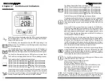
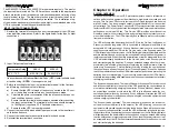
ON / OFF / TEST BUTTON:
Turning the input circuit breaker (on the
rear panel) to the on position will put the UPS in the Bypass mode and
supply power to the load. Press, hold and then release the On/Off/Test
Button during the audible alarm's first beep to turn the inverter on and
transfer the UPS to the On-Line mode. When the UPS is On, press, hold
and then release the On/Off/Test Button during the audible alarm's sec-
ond beep to turn the inverter off and transfer the UPS to the Bypass mode.
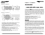
To turn the UPS off turn off the input circuit breaker on the rear panel, wait
for approximately 1-minute until the LCD and the fans turn off, and then
turn off the DC breaker(s) on the rear panel of the Battery Pack(s). When
the UPS is in the On-Line mode or the Economy mode, press, hold and
then release the On/Off/Test Button during the audible alarm's forth beep.
The UPS will perform a 10-second Self Test. During the test, the UPS will
switch to the Battery mode, the On-Battery icon will illuminate and the
audible alarm will sound. If the UPS fails the test, one of the icons will
remain illuminated indicating the type of problem. The UPS will charge
the batteries while the UPS is in the Bypass mode, the On-Line mode or
the Economy mode when there is acceptable AC voltage present.
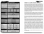
© COPYRIGHT 2014 BY PARA SYSTEMS, INC.
All Rights Reserved. All rights of this User Manual (“Manual”), including but not
limited to the content, information, and figures are solely owned and reserved
by Para Systems, Inc. (“Para Systems”). The Manual can only be applied to
the operation or the use of this product. Any disposition, duplication, dissemi-
nation, reproduction, modification, translation, extraction, or usage of this
Manual in whole or in part is prohibited without the prior written permission of
Para Systems. Given that Para Systems will continuously improve and develop
the product, changes may be made to the information in this Manual at any
time without obligation to notify any person of such revision or changes. Para
Systems will make all possible efforts to secure the accuracy and the integrity
of this Manual. Para Systems disclaims any kinds or forms of warranty, guar-
antee, or undertaking, either expressly or implicitly, including but not limited to
the completeness, faultlessness, accuracy, non-infringement, merchantability
or fitness for a particular purpose of the Manual.
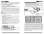
CAUTION!
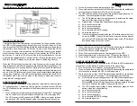
To de-energize the outputs of the UPS:
1.
If the UPS is on press and release the On/Off/Test button after the second
beep.
2.
Turn off the input circuit breaker on the rear panel of the UPS.
3.
Turn off the DC breaker(s) on the rear panel of the Battery Pack(s).
4.
Disconnect the UPS from the AC source.
5.
To completely de-energize the UPS, disconnect the battery cable.

